
Photosensitive conductive paste, method for producing multilayer electronic component using same, and multilayer electronic component

一种感光性、导电膏的技术,应用在分散在不导电无机材料中的导电材料、印刷电路制造、印刷电路零部件等方向,能够解决难以图案化、烧成收缩的程度大、光透射率降低等问题,达到防止脱层、抑制脱层、抑制收缩的效果

Active Publication Date: 2017-08-01
MURATA MFG CO LTD
View PDF7 Cites 9 Cited by
  • Summary
  • Abstract
  • Description
  • Claims
  • Application Information

AI Technical Summary

Problems solved by technology

[0005] However, when the photosensitive conductive paste of Patent Document 1 is used as the conductive paste for internal electrode formation, the firing shrinkage of the photosensitive conductive paste is lower than that of the constituent material (ceramic) of the ceramic laminate serving as the insulating layer. The degree of delamination is larger, so the occurrence of delamination may not be sufficiently suppressed. In addition, there is a problem of causing structural defects such as disconnection of electrodes due to the above-mentioned difference in firing shrinkage.
[0006] In addition, as a method of suppressing the above-mentioned firing shrinkage, it is conceivable to increase the content of the metal component particles (Ag particles) in the photosensitive conductive paste, but there is a problem that if the metal component particles (Ag particles) are increased, ) content, the light transmittance when patterning the coated photosensitive conductive paste by photolithography will decrease, making it difficult to perform fine patterning

Method used

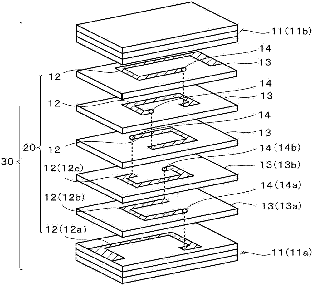
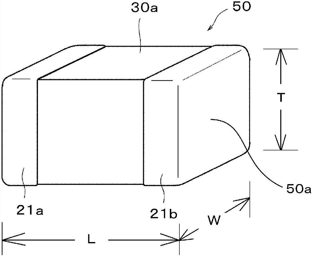
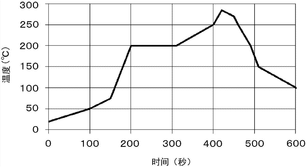

Image

  • Photosensitive conductive paste, method for producing multilayer electronic component using same, and multilayer electronic component
  • Photosensitive conductive paste, method for producing multilayer electronic component using same, and multilayer electronic component
  • Photosensitive conductive paste, method for producing multilayer electronic component using same, and multilayer electronic component

Examples


Embodiment Construction

[0038] Examples of the present invention are shown below, and the characteristic parts of the present invention will be described in more detail.

[0039] [1] Production of photosensitive conductive paste for electrode formation

[0040] In order to prepare the photosensitive conductive paste of this invention, (a) electroconductive powder, (b) photosensitive resin composition, and (c) glass frit demonstrated below are prepared.

[0041] (a) Conductive powder

[0042] As conductive powders, Ag powder (Ag powder I) having an average particle diameter of 4.0 μm and Ag powder (Ag powder II) having an average particle diameter of 2.0 μm were prepared.

[0043]Then, the sintering start temperature of Ag powder I and Ag powder II was measured by the following method. 0.5 g of Ag powder was put into a mold, and it was pressurized at a pressure of 100 MPa by a press machine to produce a granular sample. This sample was set in a TMA (Thermomechanical Analyzer: Thermodynamic Analyzer...


PUM

PropertyMeasurementUnit
softening pointaaaaaaaaaa
widthaaaaaaaaaa
particle diameteraaaaaaaaaa

Abstract

Provided is a photosensitive conductive paste which is capable of suppressing / preventing the occurrence of delamination between a conductor layer and an insulating layer even in cases where this photosensitive conductive paste is used for the formation of the conductor layer if a multilayer electronic component having a conductor layer and an internal conductor layer is produced by an integral firing process, and which enables fine patterning. This photosensitive conductive paste contains (a) a conductive powder in an amount of from 70.3% by mass to 85.6% by mass (inclusive) of the total mass of the paste, (b) a photosensitive resin composition containing an alkali-soluble polymer, a photosensitive monomer, a photopolymerization initiator and a solvent, and (c) a glass frit, and this photosensitive conductive paste is configured so as to satisfy such requirements that the mass ratio of the glass frit to the conductive paste, namely (glass frit / conductive paste) is from 0.020 to 0.054 (inclusive) and the softening point of the glass frit is not lower than the sintering initiation temperature of the conductive powder. As the glass frit, one having a softening point of 560 DEG C or more is used.

Description

technical field [0001] The invention of the present application relates to a photosensitive conductive paste for forming a conductor pattern such as a desired circuit and electrodes on a base material, a method of manufacturing a multilayer electronic component using the photosensitive conductive paste, and a multilayer electronic component. Background technique [0002] In recent years, a method of producing a laminated ceramic circuit board using a photosensitive conductive paste has been widely used, and a photosensitive conductive paste such as that described in Patent Document 1 has been proposed as one of such photosensitive conductive pastes. [0003] The photosensitive conductive paste of Patent Document 1 is a photosensitive conductive paste containing metal component particles (Ag particles), a resin having an acidic functional group, and a photoreactive organic component. The photosensitive conductive paste is composed of (a) metal component particles The central ...

Claims


Application Information

Patent Timeline
Patent Type & Authority Applications(China)
IPC IPC(8): G03F7/004C03C8/18G03F7/40H01B1/22H05K1/09
CPCC03C3/076C03C3/089C03C3/091C03C8/02C03C8/04C03C8/18C09D5/24G03F7/0047G03F7/029G03F7/031G03F7/033H01B1/22H05K1/095H05K3/02H05K3/4629H05K2203/0514B05D5/12G03F7/038H05K1/028
Inventor 近藤健太阪田智则久保田正博元家真知子
Owner MURATA MFG CO LTD
Learn More