
Heat-dissipating substrate and method for manufacturing same

A heat-dissipating substrate and manufacturing method technology, applied in semiconductor/solid-state device manufacturing, transportation and packaging, liquid chemical plating, etc., can solve the problems of reduced thermal conductivity, reduced thermal conductivity, hindered cooling, etc., to achieve plating Dealing with Easy Effects

Inactive Publication Date: 2017-08-01
SUPERUFO291 TEC
View PDF12 Cites 0 Cited by
  • Summary
  • Abstract
  • Description
  • Claims
  • Application Information

AI Technical Summary

Problems solved by technology

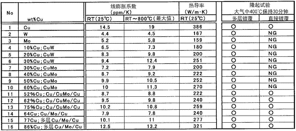
However, these composite materials all have the following problem: in order to obtain a linear expansion coefficient suitable for semiconductor devices, the thermal conductivity is greatly reduced compared with Cu
[0009] However, CuW has the following problem: the thermal conductivity at RT is 200W / m·K or less, which is significantly lower than that of Cu, so the thermal conductivity has been improved.
[0012] On the other hand, CuMo has the advantage that the specific gravity of Mo is smaller than that of W and the powder price is also cheap. However, due to poor wettability with Cu, there is a problem that the relative density (actual The ratio of the density to the theoretical density assuming that the raw material powder is completely densified) becomes small, and a material that satisfies the characteristics and quality required as a heat dissipation substrate cannot be obtained.
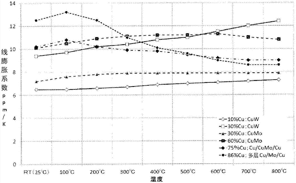
However, the case of CuMo also has the following problem: the high thermal conductivity material (Table 1) with the ratio of Cu increased to 50wt% Cu or more has a linear expansion coefficient exceeding 10ppm / K when the temperature is increased
However, it is known that there are problems in the lifetime and performance of semiconductor components based on the fact that warping occurs due to the bimetallic phenomenon, and that the high thermal conductivity material has a high peak in the coefficient of linear expansion at a temperature between 100°C and 200°C ( figure 1 ) and the value exceeds 10ppm / K; in addition, the thermal conductivity in the thickness direction is reduced due to the Mo layer with low thermal conductivity in the cross-section
However, currently there is no heat dissipation substrate material of CuW and CuMo that meets the above necessary conditions.
[0020] Since AlSiC has insufficient heat resistance, it cannot be brazed with silver, and as the temperature increases, the thermal conductivity of SiC, which is the main component, decreases significantly, so it is a problem as a heat dissipation substrate for high-performance semiconductor components
[0021] In addition, metal diamond-based heat dissipation substrate materials have heat dissipation substrate materials that meet the required characteristics, but there are problems such as difficulty in ensuring the quality of Ni-based plating, and high prices, making them unsuitable for practical use.
[0022] In addition, heat dissipation substrates for high-performance components have the following problems: when semiconductor devices are soldered, if there are many pores, cooling will be hindered, and damage and peeling will occur due to the heat of semiconductor devices.
[0030] When the linear expansion coefficient of CuMo is the same as that of CuW, the thermal conductivity is poor, and there is a problem that it is set to 50 wt% in order to make it 10 ppm / K or less as a suitable linear expansion coefficient (linear expansion coefficient suitable for semiconductor devices) When the composition is less than Cu, it is difficult to produce a composite material with a relative density of 90% or more by sintering
[0039] However, in materials with high thermal conductivity, there is a problem that although the coefficient of linear expansion at high temperature is a small value, there is a peak of the coefficient of linear expansion around 100 to 200°C, exceeding 10ppm, which is a suitable linear expansion coefficient. / K
In addition, there is a problem that the thermal conductivity in the thickness direction is small compared to the planar direction.
Furthermore, if the upper and lower sides of the cladding material are not balanced, if the temperature rises, the structure will warp due to the bimetallic effect, causing problems in performance and life.

Method used


Image

  • Heat-dissipating substrate and method for manufacturing same
  • Heat-dissipating substrate and method for manufacturing same
  • Heat-dissipating substrate and method for manufacturing same

Examples


Embodiment 1

[0122] (Example 1; CuMo with 40 wt% Cu, infiltration / densification / rolling, sample No. 6)

[0123] 3 wt% of 10 μm electrolytic Cu powder and 1 wt% of solid paraffin were mixed with Mo powder having an average particle size of 60 μm, and the obtained mixed powder was press-molded in a mold of 50 mm×50 mm, and the molded body was heated at 600° C. in hydrogen 60 minutes and dewax. Furthermore, it heated at 1000 degreeC in hydrogen gas, and produced the skeleton. A Cu plate was placed in the frame, and heated at 1250° C. for 60 minutes in a hydrogen atmosphere to infiltrate Cu. A 50 mm x 50 mm x 6 mm CuMo alloy composite was fabricated from 40 wt% Cu in this manner. Excess infiltrated Cu remaining on the surface layer of the alloy composite and defects in the surface layer were removed by cutting. This alloy composite was placed in a SUS box and degassed, and then the ends were welded and canned. It was cross-rolled at 800°C, taken out when the relative density of the alloy c...

Embodiment 2

[0128] (Example 2; CuMo with 40 wt% Cu, sintering / densification / rolling, sample No. 7)

[0129] Using Mo powder with an average particle size of 60 μm and electrolytic Cu powder with 10 μm, the powders were mixed at a compounding ratio of 40 wt % Cu and the balance Mo, and the obtained mixed powder was compression-molded with a mold of 50 mm×50 mm. The obtained compact was liquid-phase sintered at 1250° C. for 60 minutes in hydrogen to produce a CuMo alloy composite of 50 mm×50 mm×6 mm. Defects in the surface layer of the alloy composite were removed by cutting, the alloy composite was placed in a SUS case, degassed, and then the ends were welded for canning. It was cross-rolled at 800°C, taken out when the relative density of the alloy composite body reached above 99%, and solid-phase sintered at 950°C for 60 minutes in hydrogen. This alloy composite was subjected to 10 μm Cu plating treatment, and then cross-rolled at 400° C. to obtain a plate with a thickness of 2 mm. Tha...

Embodiment 3

[0133] (Example 3; CuW with 45wt% Cu, sintering / rolling, sample No. 20)

[0134] W powder with an average particle size of 60 μm and electrolytic Cu powder with 10 μm were mixed at a compounding ratio of 45 wt % Cu and the balance W, and the obtained mixed powder was compression-molded with a mold of 50 mm×50 mm. The compact was liquid-phase sintered at 1250° C. for 60 minutes in hydrogen to obtain a CuW alloy composite body of 50 mm×50 mm×6 mm.

[0135]Defects in the surface layer of the alloy composite were removed by cutting, the alloy composite was placed in a SUS case, degassed, and then the ends were welded for canning. It is cross-rolled at 800° C., taken out when the relative density of the alloy composite body reaches above 99%, and solid-phase sintered at 1000° C. for 60 minutes in hydrogen. This alloy composite was subjected to a 10 μm Cu plating treatment, and then cross rolled at 600° C. to a thickness of 2 mm. That is, the rolling reduction (=(6mm-2mm) / 6mm) of ...


PUM

PropertyMeasurementUnit
thicknessaaaaaaaaaa
melting pointaaaaaaaaaa

Abstract

A heat-dissipating substrate is manufactured by densifying and then cross-rolling an alloy composite of CuMo or CuW, comprising Cu and coarse-grain Mo or coarse-grain W, whereby the maximum value of the linear expansion coefficient from room temperature to 800 DEG C in any direction within the plane parallel to the surface of the substrate is 10 ppm / K or less, and the thermal conductivity thereof at 200 DEG C is 250 W / m*K or more.

Description

technical field [0001] The present invention relates to a heat dissipation substrate of CuMo or CuW, and a manufacturing method thereof. The heat dissipation substrate of CuMo or CuW is mounted on a semiconductor package (hereinafter referred to as a package, sometimes referred to as PKG) of a high-performance semiconductor component, and has ( 1) A coefficient of linear expansion suitable for semiconductor components and (2) a large thermal conductivity, and (3) a metal layer with few defects on the surface. Background technique [0002] Semiconductor components are used in LSI, IGBT power semiconductors, radio / optical communication semiconductors, lasers, LEDs, sensors, etc., and their structures vary depending on the performance required for them. Semiconductor components are very high-precision instruments made of materials with different linear expansion coefficients and different thermal conductivity. For the heat dissipation substrate used in the PKG, many kinds of co...

Claims


Application Information

Patent Timeline
Patent Type & Authority Applications(China)
IPC IPC(8): H01L23/373H01L23/12H01L23/36B22F1/05
CPCH01L23/12H01L2924/0002H01L23/3736C22C27/04C22F1/18B22F1/05H01L2924/00B22F3/16C22C1/045C23C18/32C23C18/38H01L21/4871H01L23/3735
Inventor 福井彰
Owner SUPERUFO291 TEC
Learn More