Fiber cladding power filter and manufacturing method thereof

A technology for optical fiber cladding and manufacturing methods, which is applied in the field of cladding power filters, can solve problems such as hot spots, property changes, filter stability, and reliability are greatly affected, and achieve improved strength and bending toughness , Guarantee the effect of safe work

Inactive Publication Date: 2017-08-11
GUANGDONG UNIV OF TECH
View PDF9 Cites 5 Cited by
  • Summary
  • Abstract
  • Description
  • Claims
  • Application Information

AI Technical Summary

Problems solved by technology

However, since the cladding power that needs to be filtered out in high-power fiber lasers can reach more than 100W, and most of the cladding power will be filtered out in a small section of the front end of the filter, this will cause the local temperature of the filter to rise sharply, while Ultraviolet glue made of organic matter is prone to property changes at high temperatures, which has a great impact on the reliability of the filter
However, other manufacturing methods of cladding power strippers, such as hydrofluoric acid etching method and high refractive index matrix method, have too many uncontrollable factors in the process of manufacturing and using, which may easily cause problems such as uneven stripping and local hot spots. The stability and reliability of the remover are greatly affected, and it is not suitable for high-power fiber lasers

Method used


Image

  • Fiber cladding power filter and manufacturing method thereof
  • Fiber cladding power filter and manufacturing method thereof
  • Fiber cladding power filter and manufacturing method thereof

Examples


Embodiment 1

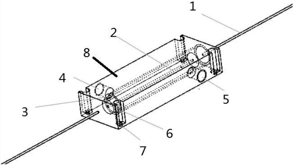
[0026] like Figure 1-3 As shown, a fiber cladding power filter, its principle is: the residual pump light and high-order laser light in the inner cladding of the optical fiber will leak out after treatment, and the light energy will be converted into heat energy on the surface of the inner hole of the heat sink. Then the water in the water channel will conduct the heat away; specifically, the optical fiber cladding power filter includes a double-clad optical fiber (1) and a heat sink (8) to filter cladding light, and the heat sink ( 8) There is an inner hole inside, and the inner hole is air or liquid. The light leaked from the optical fiber will be converted into heat energy at the interface between the inner hole and the air or liquid, without increasing the surface temperature of the optical fiber, ensuring that the optical fiber will not Melted and destroyed due to high temperature; a water channel layer (3) is provided around the inner hole, and the side wall of the heat...

Embodiment 2

[0029] like Figure 1-3 Shown, the manufacturing method of optical fiber cladding power filter comprises the steps:

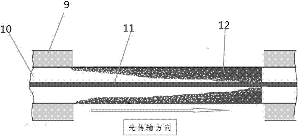
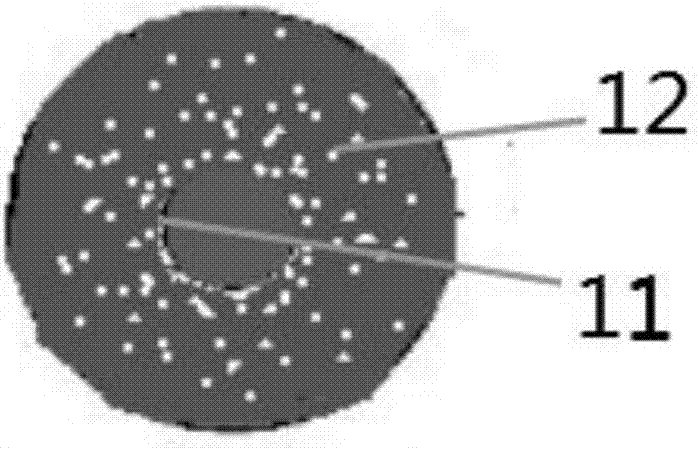
[0030] S1: Stripping a section of the outer cladding (9) of the double-clad optical fiber (1) to be filtered to expose the inner cladding (10);

[0031] S2: processing the exposed inner cladding (10), immersing the exposed inner cladding (10) in nitrate powder containing low polarizability ions;

[0032] S3: heating the exposed inner cladding (10) treated in S2;

[0033] S4: Encapsulating the double-clad optical fiber after the thermal diffusion treatment in step S3 into a heat sink (8).

[0034] After the treatment in step S2, place the exposed inner cladding (10) in liquid or air and coat the tail end of the exposed inner cladding (10) with UV glue.

[0035] In step S2, the polarizability ion of the nitrate powder is 0.003C·m2 / V.

[0036] In step S3, when heating, the double-clad optical fiber is placed in a high-temperature-resistant crucible, and then t...

Embodiment 3

[0041] like Figure 1-3 Shown, the manufacturing method of optical fiber cladding power filter comprises the steps:

[0042] S1: Stripping a section of the outer cladding (9) of the double-clad optical fiber (1) to be filtered to expose the inner cladding (10);

[0043] S2: processing the exposed inner cladding (10), immersing the exposed inner cladding (10) in nitrate powder containing low polarizability ions;

[0044] S3: heating the exposed inner cladding (10) treated in S2;

[0045] S4: Encapsulating the double-clad optical fiber after the thermal diffusion treatment in step S3 into a heat sink (8).

[0046] After the treatment in step S2, place the exposed inner cladding (10) in liquid or air and coat the tail end of the exposed inner cladding (10) with UV glue.

[0047] In step S2, the polarizability ion of the nitrate powder is 0.035C·m2 / V.

[0048] In step S3, when heating, the double-clad optical fiber is placed in a high-temperature-resistant crucible, and then the...


PUM


Abstract

The invention discloses a fiber cladding power filter, which comprises a double-cladding fiber, the cladding light of which is to be filtered, and a heat sink. The heat sink is internally provided with an inner hole; a water channel layer is arranged around the inner hole; the side wall of the heat sink is provided with a water inlet and a water outlet communicated with the water channel layer; the two ends of the heat sink are respectively provided with a fiber fixation member; and the fiber fixation members enable a fiber, one section of which is stripped to expose an inner cladding, in the double-cladding fiber, the cladding light of which is to be filtered, to be placed and sealed in the heat sink. The manufacturing method of the fiber cladding power filter comprises the following steps: S1) stripping one section of an outer cladding of the double-cladding fiber, the cladding light of which is to be filtered, to expose the inner cladding; S2) processing the exposed inner cladding; S3) heating the exposed inner cladding processed in the step S2); and S4) packaging the double-cladding fiber obtained after heat diffusion treatment in the step 3) into the heat sink. The cladding refractive index of the double-cladding fiber is modified, and laser in the cladding can be filtered efficiently and reliably.

Description

technical field [0001] The invention relates to a cladding power filter which is used in a high-power fiber laser and is manufactured by using the principle of ion replacement. Background technique [0002] In recent years, with the wide application of fiber lasers in material processing and military equipment, fiber lasers are required to have higher beam quality and longer service life while their power continues to rise. The cladding of the fiber at the output end of the fiber laser not only contains residual pump power, but also high energy generated by nonlinear effects such as spontaneous emission (ASE), Raman scattering (SRS), and Burillouin scattering (SBS). order laser. These have a negative impact on the working performance of the laser, and may cause damage to the output end face of the fiber, destroying the rear-end collimation and focusing optical path of the fiber laser. The laser power can even reach more than 100W. If these powers are not filtered before the...

Claims


Application Information

Patent Timeline
Patent Type & Authority Applications(China)
IPC IPC(8): G02B6/245H01S3/067H01S3/042
CPCG02B6/245H01S3/0407H01S3/042H01S3/06716
Inventor 龚凯郝明明李京波
Owner GUANGDONG UNIV OF TECH
Why Eureka
Try Eureka