Node equipment port expansion system and node equipment port expansion method based on optical fiber interconnection

A technology of port expansion and node equipment, which is applied in the field of node equipment port expansion system based on optical fiber interconnection, to achieve the effect of reducing the forwarding level, reducing the number of interconnection cables, and extending the bus transmission distance

Active Publication Date: 2017-08-29
XIAN MICROELECTRONICS TECH INST
View PDF6 Cites 9 Cited by
  • Summary
  • Abstract
  • Description
  • Claims
  • Application Information

AI Technical Summary

Problems solved by technology

[0007] Aiming at the problems existing in the prior art, the present invention provides a node device port expansion system and method based on optical fiber interconnection, which can meet the development of the next technology and the increasing demand for ports, and solve the problem that ports are difficult to expand, and can realize Effective Port Expansion and Optical Fiber Media Interconnection Based on SpaceWire Node Devices

Method used


Image

  • Node equipment port expansion system and node equipment port expansion method based on optical fiber interconnection
  • Node equipment port expansion system and node equipment port expansion method based on optical fiber interconnection
  • Node equipment port expansion system and node equipment port expansion method based on optical fiber interconnection

Examples


example 1

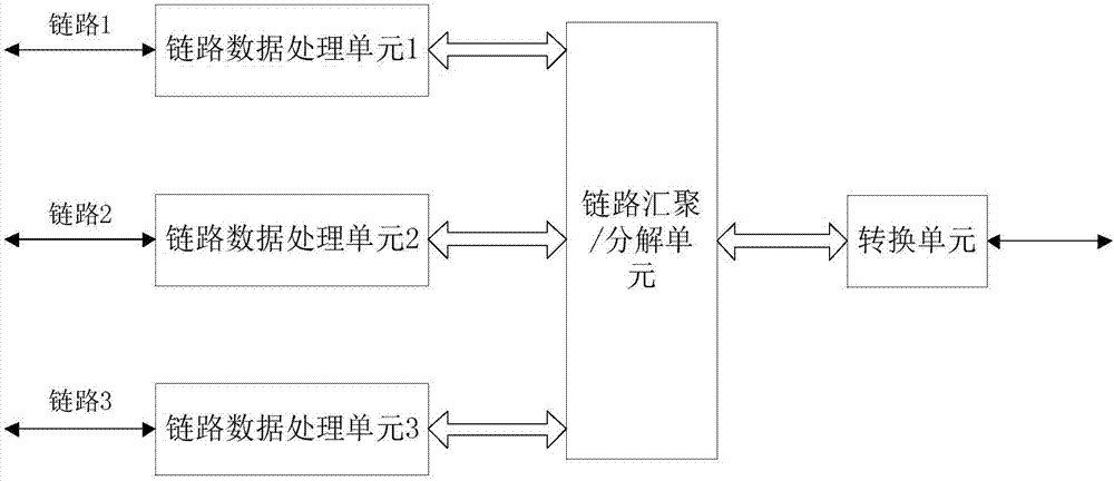
[0057] A specific example of the present invention is figure 1 As shown, it includes link data processing units 1-3, link aggregation / decomposition unit, and conversion unit.

[0058] Among them, the link data processing units 1~3 realize the data receiving / sending and conversion of links 1~3, including data receiving and sending modules, which can decode link data / strobe signals, convert them into parallel data, and The data sent by the link aggregation / decomposition unit can also be sent to the link aggregation / decomposition unit according to the link identification 1~3 to receive the data matching the link, and convert the parallel data into a serial Line data / strobe signals are sent to links 1-3.

[0059] The link aggregation / decomposition unit is used to realize the data aggregation or data decomposition of the link data processing units 1 to 3, including the link aggregation module and the decomposition module, and the parallel data and link identification sent by the l...

example 2

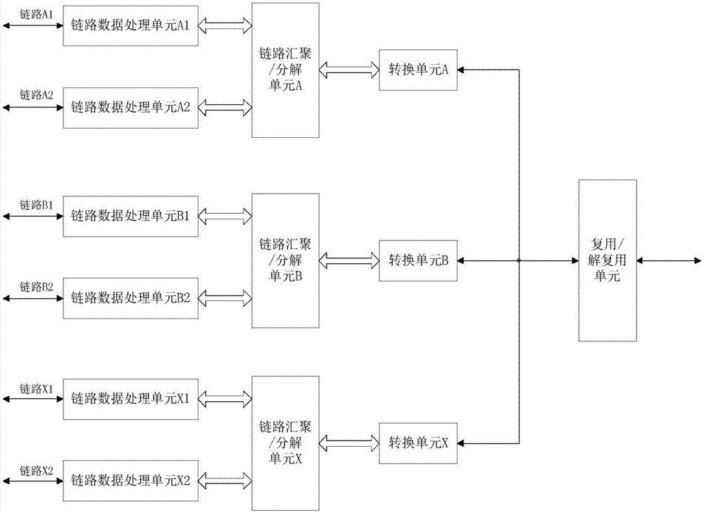
[0063] Another specific embodiment of the present invention is figure 2 As shown, it includes link data processing units A1-A2, B1-B2, X1-X2, link aggregation / decomposition units A, B, X, conversion units A, B, X, and multiplexing / demultiplexing units.

[0064] Among them, the link data processing units A1~A2, B1~B2, X1~X2 realize data reception / send and conversion of links A1~A2, B1~B2, X1~X2, including data reception and transmission modules, which can link The data / strobe signal is decoded, converted into parallel data, and sent to link aggregation / decomposition units A, B, and X respectively with link identifications 1 to 6; link aggregation / decomposition units A, B, and X can also be sent to According to the link identifiers 1~6, the incoming data receives the data matching the link, and converts the parallel data into serial data / strobe signals and sends them to the links A1~A2, B1~B2, and X1~X2 respectively.

[0065] Use link aggregation / decomposition units A, B, X to...

example 3

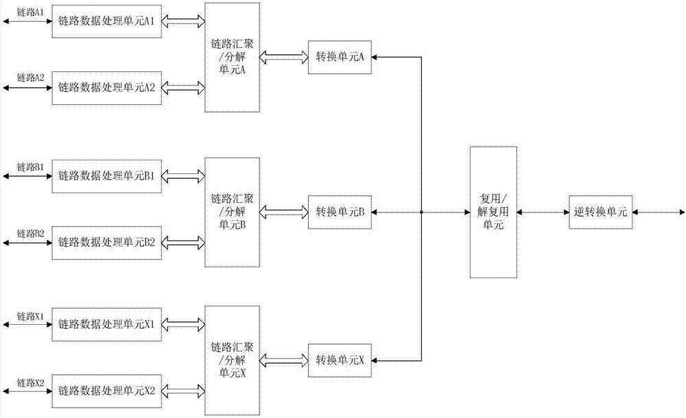
[0070] Another specific embodiment of the present invention is image 3 As shown, it includes link data processing units A1~A2, B1~B2, X1~X2, link aggregation / decomposition units A, B, X, conversion units A, B, X, multiplexing / demultiplexing units, reverse conversion unit.

[0071] Among them, the link data processing units A1~A2, B1~B2, X1~X2 realize data reception / send and conversion of links A1~A2, B1~B2, X1~X2, including data reception and transmission modules, which can link The data / strobe signal is decoded, converted into parallel data, and sent to link aggregation / decomposition units A, B, and X respectively with link identifications 1 to 6; link aggregation / decomposition units A, B, and X can also be sent to According to the link identifiers 1~6, the incoming data receives the data matching the link, and converts the parallel data into serial data / strobe signals and sends them to the links A1~A2, B1~B2, and X1~X2 respectively.

[0072] Use link aggregation / decomposi...


PUM


Abstract

A node equipment port expansion system based on optical fiber interconnection belongs to the node equipment field in a data network. The node equipment port expansion system based on optical fiber interconnection comprises a plurality of link data processing units, a link converging / decomposing unit and a converting unit. The plurality of link data processing units are converged at the link converging / decomposing unit. The link converging / decomposing unit and the converting unit are converged. The node equipment port expansion system and the node equipment port expansion method have advantages of effectively reducing number of interconnected cables in node equipment port expansion, increasing bus transmission distance, reducing system expansion cost, reducing the number of network data forwarding layers, satisfying a requirement for in-time processing and transmitting high data volume in a network system, facilitating construction of the network system based on SpaceWire node equipment, improving stability and data transmission efficiency of the network system, and realizing optical fiber interconnection of the system.

Description

technical field [0001] The invention relates to node equipment in a data network, in particular to a node equipment port expansion system and method based on optical fiber interconnection. Background technique [0002] SpaceWire is a high-speed, point-to-point, full-duplex serial bus based on two commercial standards, IEEE 1355-1995 and LVDS (Low Voltage Differential Signaling), and has the characteristics of low cost, high reliability and flexible structure. The characteristics of space applications, in addition to having good anti-electromagnetic interference characteristics, corresponding enhancements have been made in error detection, exception handling, fault protection and recovery, and have been applied in many remote sensing and commercial satellites in Europe, the United States and Japan . The SpaceWire standard is dedicated to the processing of spacecraft payload system data and control information to meet the goal of future high-performance data transmission, and...

Claims


Application Information

Patent Timeline
Patent Type & Authority Applications(China)
IPC IPC(8): H04B10/278H04J14/02
CPCH04B10/278H04J14/028
Inventor 陈卫国王剑峰刘欢
Owner XIAN MICROELECTRONICS TECH INST
Why Eureka
Try Eureka