Equipment system applicable to continuous capture of CO2 in flue gas of cement kiln

A technology of CO2 and cement kiln, which is applied in the capture of perfluorocarbons/hydrofluorocarbons, cement production, climate sustainability, etc., and can solve the problems of complex structure, insufficient cleanliness, and high cost of the capture device. , to achieve the effect of simple equipment structure, no secondary pollution, and reduced operating costs

Pending Publication Date: 2017-09-01
长沙紫宸科技开发有限公司
View PDF6 Cites 9 Cited by
  • Summary
  • Abstract
  • Description
  • Claims
  • Application Information

AI Technical Summary

Problems solved by technology

[0014] The main purpose of the present invention is to provide a method suitable for CO in cement kiln flue gas 2 Equipped systems for continuous capture designed to address existing CO 2 The capture device has complex structure, insufficient cleanliness, high energy consumption, and high cost, which are difficult to popularize

Method used


Image

  • Equipment system applicable to continuous capture of CO2 in flue gas of cement kiln
  • Equipment system applicable to continuous capture of CO2 in flue gas of cement kiln
  • Equipment system applicable to continuous capture of CO2 in flue gas of cement kiln

Examples


Embodiment 1

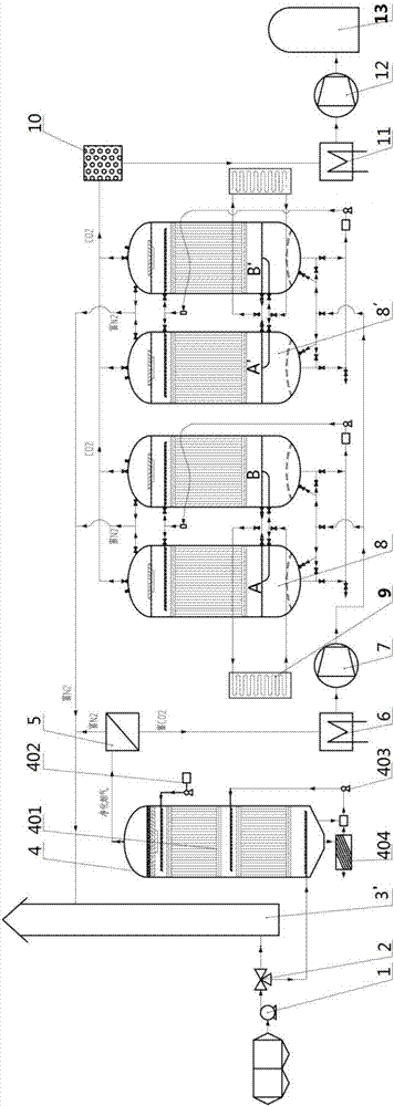
[0042] figure 1 It is applicable to the CO in the cement kiln flue gas proposed for the first embodiment of the present invention 2 Schematic diagram of the equipment system for continuous capture. figure 2 for figure 1 The proposed method is suitable for CO in cement kiln flue gas 2 CO in continuous capture systems 2 Schematic diagram of the structure of the circulation capture tower. image 3 for figure 1 The proposed method is suitable for CO in cement kiln flue gas 2 Schematic diagram of the structure of the atomizing spray device in the continuous capture equipment system. Figure 4 for figure 1 The proposed method is suitable for CO in cement kiln flue gas 2 Schematic diagram of the cooling / heating device in the continuous capture equipment system.

[0043] see Figure 1 to Figure 4 , suitable for CO in cement kiln flue gas 2 Continuous capture equipment system, including kiln exhaust fan 1, chimney 3, flue gas oxidation purifier 4, N 2 / CO 2 Membrane separ...

Embodiment 2

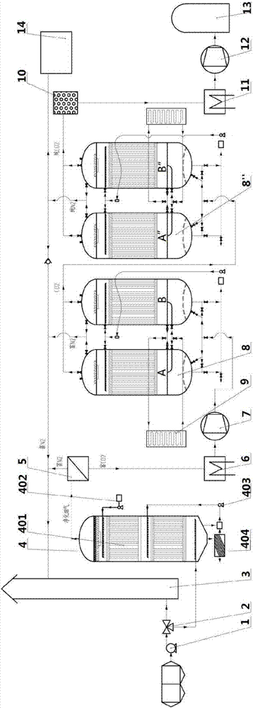
[0064] Figure 5 It is applicable to CO in cement kiln flue gas proposed for the second embodiment of the present invention 2 Schematic diagram of the equipment system for continuous capture.

[0065] see Figure 5 , the difference between the second embodiment and the first embodiment is that the CO 2 The circulation capture tower includes the same structure and is arranged in parallel by the CO 2 Circulation trap A and CO 2 There are two sets of circulating catchers B, the first set of CO 2 Circulation capture tower 8 includes CO 2 Circulation trap A and CO 2 Circulation trap B, second set of CO 2 Circulation capture tower 8' including CO 2 Circulation trap A' and CO 2 Circulating trap B', each of the CO 2 N-enriched in circulating traps (A, B, A', B') 2 The gas exhaust pipe is connected to the chimney or N 2 storage tank, each of the CO 2 CO in recirculating traps (A, B, A', B') 2 The discharge pipeline communicates with the dehydration dryer in sequence.

[...

Embodiment 3

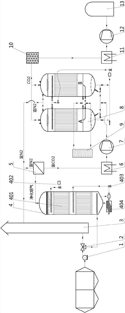
[0069] Image 6 It is applicable to CO in cement kiln flue gas proposed for the third embodiment of the present invention 2 Schematic diagram of the equipment system for continuous capture.

[0070] see Image 6 , the difference between the third embodiment and the first embodiment is that the CO 2 The circulation capture tower includes the same structure and is arranged in series by the CO 2 Circulation trap A and CO 2 There are two sets of circulating catchers B, the first set of CO 2 Circulation capture tower including CO 2 Circulation trap A and CO 2 Circulation trap B, second set of CO 2 Circulation capture tower including CO 2 Circulation trap A" and CO 2Circulation trap B", the flue gas compressor is first connected to the first set of CO 2 Circulation capture tower, the first set of the CO 2 N-rich in circulating trap tower 2 The gas exhaust pipe is connected to the chimney or N 2 Storage tank, first set of CO 2 CO from the cycle capture tower 2 The disc...


PUM


Abstract

The invention discloses an equipment system applicable to continuous capture of CO2 in flue gas of a cement kiln. The equipment system comprises a kiln end exhaust fan, a chimney, a flue gas oxidization purifier, a N2/CO2 membrane separation device, a cooler, a flue gas compressor, a CO2 cycle capture tower, a dehydration dryer, a CO2 cooler, a CO2 compressor and a liquefied CO2 storage tank, wherein the kiln end exhaust fan is communicated with a gas inlet of the flue gas oxidization purifier; a purified flue gas outlet of the flue gas oxidization purifier is communicated with a gas inlet of the N2/CO2 membrane separation device; a N2-rich discharge port of the N2/CO2 membrane separation device is communicated with the chimney; a CO2-rich discharge port of the N2/CO2 membrane separation device is sequentially communicated with the CO2 cycle capture tower by the cooler and the flue gas compressor; the CO2 cycle capture tower comprises a CO2 cycle capture releaser A and a CO2 cycle capture releaser B which alternately and continuously perform CO2 capture and CO2 release. The equipment system is simple in structure and low in construction cost, has industrial applicability, realizes clean discharge of the flue gas on a cement production line, realizes effective discharge reduction and low-carbon production of a cement enterprise, and also realizes high-efficiency and continuous CO2 capture and separation.

Description

technical field [0001] The invention belongs to the technical field of waste gas treatment devices, and in particular relates to a CO 2 Equipment system for continuous capture. Background technique [0002] Climate change has become one of the issues affecting human survival and development, and industrial emissions of carbon dioxide are considered to be the main cause of climate warming. my country, as the largest developing country in the world, uses coal as its primary energy and fire The secondary energy structure dominated by power generation, with the rapid growth of economic aggregate, the CO of primary energy and secondary energy 2 Emissions have the characteristics of fast growth and large total amount, and the current CCS (Carbon Capture and Storage, carbon capture and storage) or CCUS (Carbon Capture, Utilization and Storage, carbon capture, utilization and storage) technology for carbon emission reduction and climate change response The luck economy of high inve...

Claims


Application Information

Patent Timeline
Patent Type & Authority Applications(China)
IPC IPC(8): B01D53/75B01D53/78B01D53/72B01D53/68B01D53/64B01D53/60C01B32/50C04B7/44F27D17/00
CPCB01D53/60B01D53/64B01D53/68B01D53/72B01D53/75B01D53/78F27D17/004F27D17/008C04B7/44F27D2017/007Y02P20/129Y02P40/121Y02P40/18Y02C20/30Y02A50/20Y02P10/25Y02P20/151
Inventor 尹小林
Owner 长沙紫宸科技开发有限公司
Why Eureka
Try Eureka