
Nanofiber catalyst and preparation method thereof

A nanofiber and catalyst technology, applied in the field of nanofiber catalyst and its preparation, can solve the problems of limited effective catalyst load, low catalyst external diffusion rate, complex catalyst manufacturing process and the like

Active Publication Date: 2017-09-01
栗豹
View PDF3 Cites 3 Cited by
  • Summary
  • Abstract
  • Description
  • Claims
  • Application Information

AI Technical Summary

Problems solved by technology

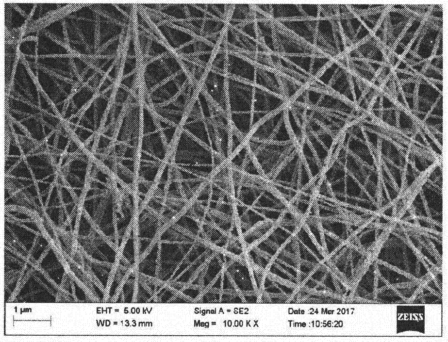
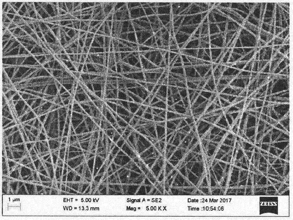
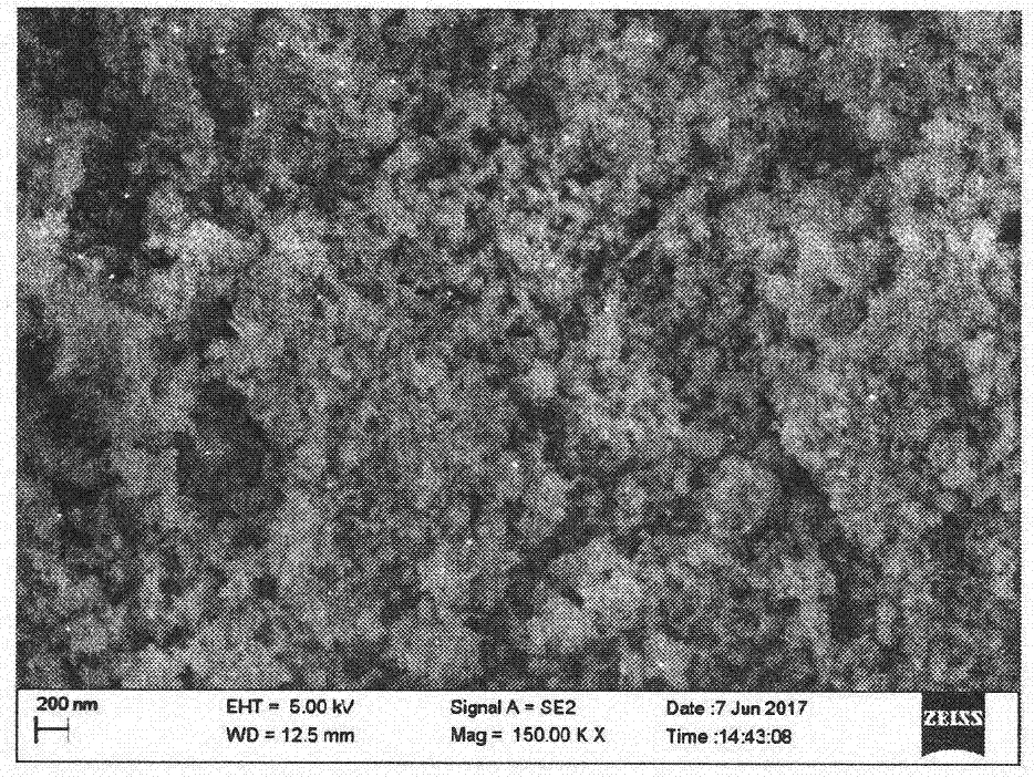
[0004] In order to solve the problem of low diffusion rate of the catalyst in the catalyst forming process, the manufacturing process of the catalyst supported by the honeycomb or corrugated plate carrier is complicated, the cost is expensive, and the effective loading amount of the catalyst per unit volume is limited, we use electrospinning method, successfully prepared nanofibrous oxide catalysts, showing good catalytic performance

Method used


Image

  • Nanofiber catalyst and preparation method thereof
  • Nanofiber catalyst and preparation method thereof
  • Nanofiber catalyst and preparation method thereof

Examples


Embodiment 1

[0039]Set Y(NO 3 ) 3 ·6H 2 O(1.8754mmol), Mn(CH 3 COO) 2 4H 2 O (3.75mmol), polyvinylpyrrolidone (PVP, K=90, 1g) was dissolved in ethanol (9mL) and deionized water (10mL), and stirred continuously at room temperature for 10h to obtain a mixed solution A;

[0040] Put the mixed solution A into the syringe pump, set the distance from the needle to the receiving plate to 15cm, adjust the voltage to 15KV, set the injection speed to 0.05mm / min, and adjust the air humidity to 15%. ) to spin the sol, then dry the spun nanofibers at a high temperature in an oven, and after cooling to room temperature, put the obtained nanofibers containing yttrium and manganese into a muffle furnace for high-temperature calcining; the heating rate setting As follows: from room temperature to 450°C at a heating rate of 25°C / h for 2 hours, then at the same heating rate to 600°C for 2 hours, to 800°C for 4 hours, and finally cool down to room temperature naturally. The nanofiber catalyst YMn can be...

Embodiment 2

[0043] will be used as Sm(NO 3 ) 3 ·6H 2 O(1.8754mmol), Mn(CH 3 COO) 2 4H 2 O (3.75mmol), polyvinylpyrrolidone (PVP, K=90, 1g) was dissolved in ethanol (9mL) and deionized water (10mL), and stirred continuously at room temperature for 10h to obtain a mixed solution B;

[0044] Put the mixed solution B into the syringe pump, set the distance from the needle to the receiving plate to 15cm, adjust the voltage to 15KV, set the injection speed to 0.05mm / min, and adjust the air humidity to 15%. ), the sol was spun out, and then the spun nanofibers were dried in an oven at a high temperature. After cooling to room temperature, the obtained nanofibers were calcined in a muffle furnace at a high temperature; the heating rate was set as follows: from room temperature to The heating rate of 25°C / h was raised to 450°C for 2 hours, then raised to 600°C for 2 hours at the same heating rate, and kept at 800°C for 4 hours, and finally cooled to room temperature naturally. Nanofiber cata...


PUM

PropertyMeasurementUnit
Diameteraaaaaaaaaa
Lengthaaaaaaaaaa
Diameteraaaaaaaaaa

Abstract

The invention relates to a lanthanide series and yttrium-bismuth composite nanofiber catalyst and a preparation method thereof. The conventional industrial catalyst is mainly synthesized by adopting a hydrothermal synthesis or co-precipitation method, only a powdery structure can be formed, and agglomeration is easy; an electrostatic spinning method is adopted for successfully spinning partial industrial catalyst to be nanofibrous, thereby being simple and convenient; meanwhile, the diameter of the nanofiber maintains to be 60-800nm, and length ranges from 0.3mu m to 30mu m and is even longer; and experimental operation is simplified, and during a NO catalysis experiment, the composite nanofiber catalyst shows higher catalytic performance compared with a sample synthesized by adopting the traditional method.

Description

technical field [0001] The invention relates to a nanofiber catalyst and a preparation method thereof. Background technique [0002] Catalysts have been widely used in various industrial production processes and environmental treatment, such as petroleum cracking, hydrogenation, catalytic oxidation, desulfurization, denitrification and other fields. Catalysts mainly include activated carbon, molecular sieves, precious metals and metal oxide catalysts, etc. Catalysts are usually synthesized by impregnation, co-precipitation, ion exchange, and hydrothermal synthesis. The catalysts produced by these synthesis methods usually exist in the form of powder, and need to be further processed by granulation, layering and other methods before they can be used. During the molding process such as granulation and layering, the catalyst will inevitably lose part of its specific surface area and catalytic performance. And since the size of the molded catalyst is usually more than a thousa...

Claims


Application Information

Patent Timeline
IPC IPC(8): B01J23/34B01D53/86B01D53/56
CPCB01D53/8628B01J23/34B01J35/40B01J35/58
Inventor 王卫超张同
Owner 栗豹
Learn More