Flue gas denitrification equipment line

A flue gas and denitrification technology, applied in gas treatment, membrane technology, dispersed particle separation, etc., can solve the problem of low denitrification rate of denitrification equipment line, achieve the effect of improving heat exchange efficiency, solving ammonia escape, and improving denitrification efficiency

Pending Publication Date: 2017-09-08
CHENGDU GUOHUA ENVIRONMENTAL TECH
View PDF13 Cites 0 Cited by
  • Summary
  • Abstract
  • Description
  • Claims
  • Application Information

AI Technical Summary

Problems solved by technology

[0005] The purpose of this application is to provide a denitration equipment line device that can improve the denitration rate in view of the problem that the denitration rate of the current denitrification equipment line is not high

Method used


Image

  • Flue gas denitrification equipment line
  • Flue gas denitrification equipment line
  • Flue gas denitrification equipment line

Examples


Embodiment 1

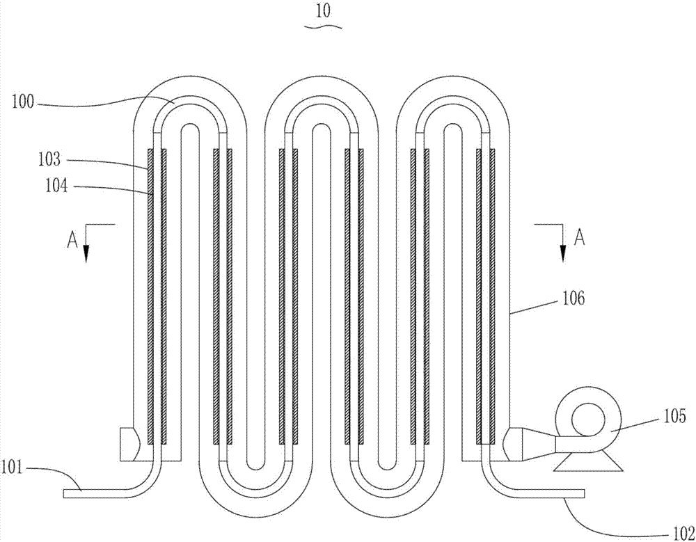
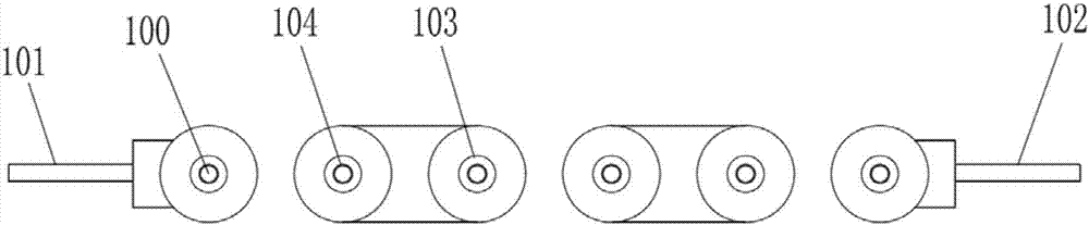
[0134] Example 1, such as figure 1 with 2 Shown:

[0135] A liquid ammonia evaporator 10 for a denitrification equipment line, comprising a liquid ammonia delivery pipe 100, one end of the liquid ammonia delivery pipe 100 is a liquid ammonia inlet port 101 connected to a liquid ammonia source, and the other end is an ammonia gas outlet port 102 A plurality of cooling fins 103 are arranged outside the liquid ammonia delivery pipe 100 .

[0136] The liquid ammonia evaporator 10 of the present embodiment, by arranging the heat dissipation fins 103 outside the liquid ammonia delivery pipe 100, increases the heat exchange area between the liquid ammonia delivery pipe 100 and the external space, so that the liquid ammonia can be more efficiently transported during the transportation process. Complete gasification forms ammonia gas, that is, the gasification rate of liquid ammonia is improved, so that the mixing adequacy of ammonia gas and flue gas is further improved, on the one h...

Embodiment 2

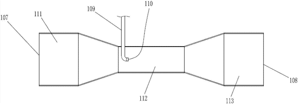
[0152] Example 2, such as image 3 as shown,

[0153] A conditioning tube for denitrification equipment line, comprising a conditioning cylinder, one end of the conditioning cylinder is a conditioning inlet 107, the other end is a conditioning outlet 108, the conditioning tube also includes an ammonia gas inlet Pipe 109, one end of the ammonia gas inlet pipe 109 extends into the tempering cylinder, and the other end is located outside the tempering cylinder.

[0154] The quenching and tempering tube of this embodiment, when in use, blows air into the quenching and tempering inlet 107 or other chemical reactions in the middle of the denitrification process to dilute the high-concentration ammonia gas to make it into a lower concentration Ammonia gas, on the one hand, directly makes the liquid ammonia gasify completely and fully, on the other hand, it is also more conducive to the uniform mixing of ammonia gas and flue gas, so as to improve the denitrification efficiency and en...

Embodiment 3

[0167] Example 3, such as Figure 4 with 5 Shown:

[0168] An ammonia injection grid used for a denitrification equipment line, comprising an ammonia injection main pipe 114, one end of the ammonia injection main pipe 114 communicates with the quenching and tempering outlet 108 of the quenching and tempering tube, and the other end is located at the inlet pipe of the denitration tower 117. In the flue gas pipeline 115 , the part of the ammonia injection main pipe 114 located in the flue gas pipeline 115 is an ammonia injection section, and several second nozzles 118 are arranged on the ammonia injection section.

[0169] The ammonia injection grid of this embodiment, through the second nozzle 118, sprays the low-concentration ammonia gas mixed with air into the flue gas pipe 115, so that the flue gas and ammonia gas are fully mixed before entering the denitrification tower 117, ensuring In the denitrification tower 117, the nitrogen oxides in the flue gas can more fully cont...


PUM


Abstract

The application relates to the technical field of air pollution control in the environmental protection industry, in particular to a flue gas denitrification equipment line. The flue gas denitrification equipment line comprises a flue gas conditioning assembly and at least one denitrification tower, wherein the denitrification tower comprises a tower body; at least one catalyst assembly is arranged in the tower body; the catalyst assembly comprises at least two silk screen assemblies; a third sealing plate is connected between opposite edges of the silk screen assemblies; the silk screen assemblies and the third sealing plate are enclosed into a second cavity for charging or discharging flue gas; first cavities of the silk screen assemblies are filled with a denitrification agent. In the flue gas denitrification equipment line disclosed by the application, the conditioning assembly and the denitrification tower with the catalyst assembly are provided, so that the denitrification efficiency in a flue gas denitrification process is increased greatly, the removal rate of nitrogen oxide in the flue gas is increased greatly, and the problem of ammonia escape due to incomplete reaction of ammonia gas is solved.

Description

technical field [0001] This application relates to the technical field of air pollution control in the environmental protection industry, in particular to a flue gas denitrification equipment line. Background technique [0002] In industrial flue gas, it usually means a large amount of nitrogen oxides, and nitrogen oxides is one of the main air pollutants, and it is also the main cause of acid rain, photochemical smog, high ground ozone concentration and greenhouse effect, which seriously damages the human health and living environment. Therefore, active research and development of flue gas denitrification technology has important environmental, economic and social benefits. [0003] At present, the removal of nitrogen oxides in the flue gas is usually achieved by using a denitration equipment line. As far as the current denitration equipment line is concerned, it mainly includes an ammonia injection device and a denitration tower connected to the ammonia injection device. ...

Claims


Application Information

Patent Timeline
Patent Type & Authority Applications(China)
IPC IPC(8): B01D53/86B01D53/56B01D53/90
CPCB01D53/8631B01D53/90B01D2251/2062B01D2258/0283
Inventor 麻强王维江王怀金李立松荀鹏王平廖玉珍李登嵩
Owner CHENGDU GUOHUA ENVIRONMENTAL TECH
Why Eureka
Try Eureka