Heating furnace visual combustion control system and method based on multi-parameter detection

A control system and control method technology, applied in the direction of controlling combustion, lighting and heating equipment, direct carbon dioxide emission reduction, etc., can solve the problems of difficult concentration of nitrogen oxides, large transient interference, and large pollution emissions, etc., to improve the device Operational efficiency, reduction of excess air content, and effect of reducing pollutant emissions

Active Publication Date: 2017-09-12
HEFEI RUISHI MEASUREMENT & CONTROL ENG TECH
View PDF8 Cites 11 Cited by
  • Summary
  • Abstract
  • Description
  • Claims
  • Application Information

AI Technical Summary

Problems solved by technology

[0002] Heating furnace is an important energy-consuming equipment in metallurgy, chemical industry, petrochemical industry, non-ferrous metals and other industries, and it is also one of the main sources of pollutants such as carbon dioxide and nitrogen oxides. Low efficiency, fast oxidation and carburization of the furnace tube surface, high pollution emissions, short service life of the furnace tube and potential safety hazards, etc. Patent CN201410341338.3 discloses a PLC-based low nitrogen oxide control method and system, according to nitrogen oxidation Compared with the actual measured value and the emission target value, the DCS controls the secondary damper opening command and the separate burn-off air SOFA damper opening command to achieve low-nitrogen combustion and optimal operation of the boiler, but it is difficult to continuously measure the concentration of nitrogen oxides online , and the structure shown in this method is only a coal-fired boiler in a power plant. Patent CN01133648.X discloses a method for optimizing the combustion of a multi-combustion furnace of a boiler. A plurality of flame image detectors are arranged in the furnace to obtain the three-dimensional temperature field distribution of the furnace. According to the state that the flame center deviates from its ideal position, the distribution control instructions of the fuel volume and air volume in the combustion furnace are given. This method collects the flame image, and the transient interference is relatively large, which requires high reliability for the simulation method of the three-dimensional temperature field of the furnace.

Method used


Image

  • Heating furnace visual combustion control system and method based on multi-parameter detection
  • Heating furnace visual combustion control system and method based on multi-parameter detection
  • Heating furnace visual combustion control system and method based on multi-parameter detection

Examples


Embodiment Construction

[0024] The technical solutions of the present invention will be described in detail below, but the protection scope of the present invention is not limited to the embodiments.

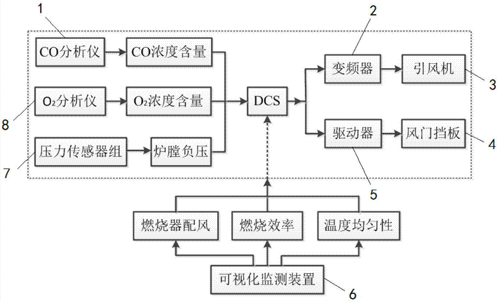
[0025] like figure 1 As shown, the visual combustion control system of the heating furnace based on multi-parameter detection of the present invention includes a CO analyzer 1 for on-line precise detection of CO content in flue gas, and an on-line detection of O in the furnace. 2 content of O 2 Analyzer 8, visual monitoring device 6, pressure sensor 7, frequency converter 2, induced draft fan 3, driver 5, damper baffle 4 and CO analyzer 1, O 2 Analyzer 8, pressure sensor 7 closed-loop control connected DCS control system, several pressure sensors 7 are installed in groups in the radiation section and convection section of the heating furnace, and the furnace pressure is determined by taking the median of the detection data of all individual pressure sensors 7 , the CO analyzer 1 and O used to detect ...


PUM


Abstract

The invention discloses a heating furnace visual combustion control system based on multi-parameter detection. The system comprises a CO analyzer for online precise detection of the content of CO in smoke, an O2 analyzer used for online detection of the content of O2 in a hearth, a visual monitoring device, a pressure sensor, a frequency converter, an induced draft fan, a driver, an air door baffle and a DCS control system, wherein the DCS control system is in closed-loop control connection with the CO analyzer, the O2 analyzer and the pressure sensor and controls the driver and the frequency converter according to the set control system safety adjusting threshold value, and the combustion state of the heating furnace is optimized and adjusted; the visual monitoring device displays the combustion state of a nozzle in the heating furnace, the combustion efficiency is estimated, the temperature uniformity and longitudinal temperature gradient of the hearth are calculated, and a control method of the heating furnace visual combustion control system is further disclosed. The multi-parameter visual combustion control method is adopted, the heating furnace is constantly in a theory close combustion state, the combustion efficiency is improved, the device running efficiency is improved, pollutant emission is reduced, and especially emission of CO2 and NOx is reduced.

Description

technical field [0001] The invention relates to a combustion system and method, in particular to a heating furnace visualization combustion control system and control method. Background technique [0002] Heating furnace is an important energy-consuming equipment in metallurgy, chemical industry, petrochemical industry, non-ferrous metals and other industries, and it is also one of the main sources of pollutants such as carbon dioxide and nitrogen oxides. Low efficiency, fast oxidation and carburization of the furnace tube surface, high pollution emissions, short service life of the furnace tube and potential safety hazards, etc. Patent CN201410341338.3 discloses a PLC-based low nitrogen oxide control method and system, according to nitrogen oxidation Compared with the actual measured value and the emission target value, the DCS controls the secondary damper opening command and the separate burn-off air SOFA damper opening command to achieve low-nitrogen combustion and optim...

Claims


Application Information

Patent Timeline
Patent Type & Authority Applications(China)
IPC IPC(8): F23N5/00
CPCF23N5/006F23N2225/04Y02E20/32
Inventor 唐磊蒋杉舒志峰冯俊生赵晓虎熊丹枫毕玉李大创仓亚军吴海滨
Owner HEFEI RUISHI MEASUREMENT & CONTROL ENG TECH
Why Eureka
Try Eureka