
Integrated energy-saving dehumidifying and heating device

A technology for heating devices and surface coolers, which is applied in the fields of food equipment, medicine, chemical industry, and materials. It can solve problems such as unstable control of process parameters, increased maintenance costs, and increased time costs, and achieves stable control of process parameters and high production efficiency. The effect of cost reduction and low maintenance cost

Pending Publication Date: 2017-09-29
SHENZHEN XINYITE SCI & TECH
View PDF3 Cites 1 Cited by
  • Summary
  • Abstract
  • Description
  • Claims
  • Application Information

AI Technical Summary

Problems solved by technology

[0004] In order to ensure product quality and meet specific process requirements, high-temperature dry gas (such as air) must be obtained. Usually, two sets of devices are used at the same time. This method has many defects: ① Equipment assembly is cumbersome and time costs increase ; ②The size of the equipment and the space occupied are large; ③The control of the process parameters is unstable; ④The number of accessories and wearing parts increases, and the maintenance cost increases; ⑤The energy consumption increases greatly

Method used


Image

  • Integrated energy-saving dehumidifying and heating device
  • Integrated energy-saving dehumidifying and heating device

Examples


Embodiment 1

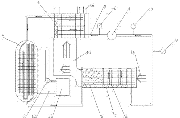
[0021] combined with figure 1 According to an integrated energy-saving dehumidification heating device of the present invention, it consists of 1-compressor, 2-high pressure gauge, 3-freon pipeline, 4-air-cooled surface cooler, 5-volute tube type surface cooler, 6- Capillary tube, 7-air-cooled air box, 8-evaporator, 9-oil and gas separator, 10-low pressure gauge, 11-water tower water pump, 12-water tower circulating water pipe, 13-water tower, 14-normal temperature and humidity air, 15-air duct , 16-Air duct for equipment.

[0022] The refrigerant is compressed by the 1-compressor, and cooled and dehumidified by the 14-normal temperature and humidity wind through the 8-evaporator to obtain dry cold air.

[0023] The dry cold air diffuses into the 4-air-cooled surface cooler, and the dry cold air is heated by the high temperature generated by the compressed refrigerant of the 1-compressor.

[0024] After the heat exchange, the higher temperature refrigerant is cooled again th...

Embodiment 2

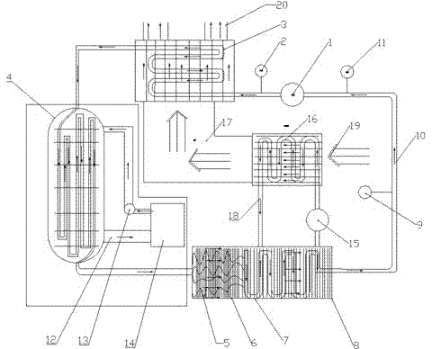
[0027] combined with figure 2 , according to an integrated energy-saving dehumidification heating device of the present invention, it consists of 1-compressor, 2-high pressure gauge, 3-air-cooled surface cooler, 4-volute tube type surface cooler, 5-capillary tube, 6-refrigerating Water, 7-Evaporator, 8-Water tank, 9-Oil and gas separator, 10-Freon pipeline, 11-Low pressure gauge, 12-Water tower chilled water pipeline, 13-Water tower pump, 14-Water tower, 15-Water cooling table cooler pump , 16-water-cooled surface cooler, 17-air duct, 18-water-cooled surface cooler water pipe, 19-normal temperature and humidity wind, 20-air duct for equipment.

[0028] The refrigerant is compressed by the 1-compressor, the water in the 8-water tank is cooled by the 8-evaporator, and the cold water is pumped into the 6-water-cooled surface cooler by the 15-water-cooled surface cooler water pump to cool and dehumidify the normal temperature and humidity gas , get dry cold air.

[0029] The dr...


PUM


Abstract

The invention discloses an integrated energy-saving dehumidifying and heating device. The integrated energy-saving dehumidifying and heating device structurally comprises an air inlet / outlet pipeline, an evaporator, an air-cooling surface cooler, a compressor, a low-pressure gauge, a high-pressure gauge and an oil-gas separator. The integrated energy-saving dehumidifying and heating device can further comprise other auxiliary structures. According to the designed novel energy-saving dehumidifying and heating device, the dehumidifying and heating process is completed completely through internal energy conversion, specifically, normal-temperature and normal-humidity gas is cooled and dehumidified through high-pressure compression of refrigerants, so that dry cold air is obtained, the dry cold air diffuses to enter the air-cooling surface cooler, the dry cold air is heated through high temperature generated when the compressor compresses the refrigerants, reutilization is achieved in this way, and the purposes of simple structure, small occupied area, stable control over technological parameters, low maintenance cost, and dehumidifying and heating at extremely-low energy consumption are achieved.

Description

technical field [0001] The invention relates to an integrated energy-saving dehumidification heating device, in particular to equipment for heating and dehumidifying process gas (such as air), and belongs to the fields of medicine, chemical industry, materials and food equipment. Background technique [0002] At present, in the fields of medicine, chemical industry, materials, food, etc., it is often necessary to pretreat the normal temperature gas (such as: air) to meet the production process requirements, especially in the drying, coating and other processes of the pharmaceutical industry, it is necessary to use hot gas ( Such as: air), to evaporate water or solvent, humidity plays a vital role in drying, coating efficiency and final moisture balance. And under the high temperature and high humidity environment, due to the high absolute humidity of the air, the quality and efficiency of drying and coating cannot be reliably guaranteed, and gas (such as: air) dehumidificati...

Claims


Application Information

Patent Timeline
Patent Type & Authority Applications(China)
IPC IPC(8): F24F1/02F24F12/00
CPCF24F3/1405F24F3/153F24F12/00F24F2003/144
Inventor 刘海周伟
Owner SHENZHEN XINYITE SCI & TECH
Learn More