Microwave photonic image frequency rejection mixing method and device

A technology of image frequency suppression and microwave photonics, which is applied in the directions of multi-frequency modulation and conversion, optical fiber transmission, optical fiber radio, etc. It can solve the problem of inseparability, reduce complexity and cost, realize frequency conversion efficiency, and realize flexible and changeable methods. Effect

Active Publication Date: 2017-10-03
NANJING UNIV OF AERONAUTICS & ASTRONAUTICS
View PDF3 Cites 21 Cited by
  • Summary
  • Abstract
  • Description
  • Claims
  • Application Information

AI Technical Summary

Problems solved by technology

However, only the image frequency component, RF and LO leakage components in the spurious components have been discussed so far
(Z.Z.Tang, and S.L.Pan, "A Compact Image-Reject and Single-Sideband Mixer with Suppression of LO Leakage Based on A Dual-Polarization Dual-Drive Mach-Zehnder Modulator," in the Avionics and Vehicle Fiber-Optics and PhotonicConference and the International Topical Meeting on Microwave Photonics 2016 (AVFOP&MWP 2016), Oct.31-Nov.3, 2016, Long Beach, California, USA) and other spurious components are not reported, such as the double intermediate frequency generated by the image frequency and signal component, and the double intermediate frequency component will be seriously aliased into the intermediate frequency signal when the broadband signal is mixed, and it cannot be separated in the frequency domain
[0004] On the other hand, the modulation format of the signal is often limited to meet the suppression of spurs or the improvement of frequency conversion efficiency
Due to the need to prevent local oscillator and radio frequency leakage, it is often required to implement carrier-suppressed single-sideband modulation for the frequency-conve

Method used


Image

  • Microwave photonic image frequency rejection mixing method and device
  • Microwave photonic image frequency rejection mixing method and device
  • Microwave photonic image frequency rejection mixing method and device

Examples


Embodiment 1

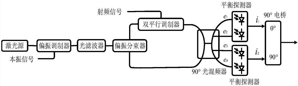
[0075] Such as figure 2 As shown, the frequency mixing device of this embodiment includes a light source (continuous wave laser), a polarization modulator, an optical filter, a polarization beam splitter, a dual parallel modulator, a 90° optical mixer, two balanced detectors, 90 °Microwave bridge.

[0076] The optical carrier ω output by the continuous wave laser c Injected into the polarization modulator, the local oscillator signal ω to be mixed L It is modulated on the optical carrier through the polarization modulator, and the output signal is injected into the optical filter, and the optical filter outputs the optical signal including the carrier and the upper sideband. After the optical signal passes through the polarization beam splitter, the optical carrier and the upper sideband are respectively output from two output ports of the polarization beam splitter.

[0077] The upper sideband of the local oscillator output by the polarizing beam splitter is expressed as ...

Embodiment 2

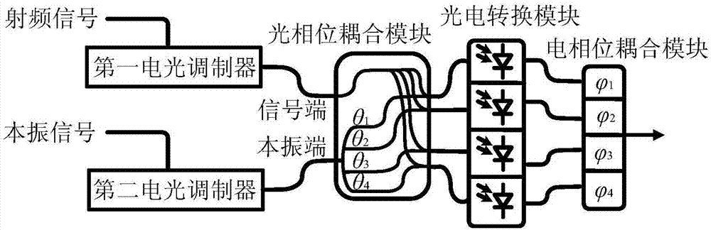
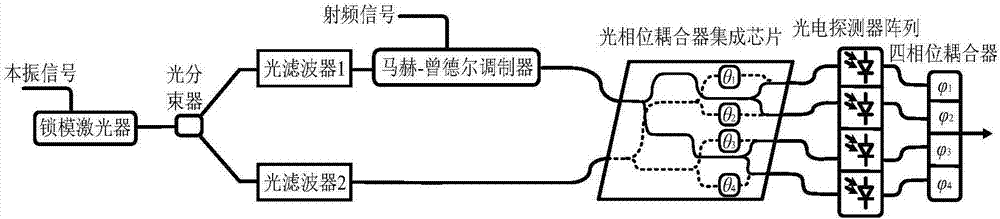
[0107] Such as image 3 As shown, the frequency mixing device in this embodiment includes: a mode-locked laser, an optical beam splitter, an optical filter 1, an optical filter 2, a Mach-Zehnder modulator, an optical phase coupling module, and four photodetectors A photodetector array (that is, a photoelectric conversion module) and a four-phase coupler are formed.

[0108] First set the frequency to ω L The local oscillator signal is injected into the mode-locked laser to generate an optical frequency comb whose comb tooth interval is the local oscillator frequency, and then its output is divided into two paths through the optical beam splitter, and two channels are selected by optical filter 1 and optical filter 2 respectively. frequency is ω c and ω c +ω L frequency components. Set the frequency to ω c The optical signal is double-band modulated by the radio frequency signal through the Mach-Zehnder modulator. The frequency of the modulated RF signal is ω s , while ...


PUM


Abstract

The invention discloses a microwave photonic image frequency rejection mixing method which comprises the steps of: respectively regulating a radio frequency signal and a local oscillation signal which are to be mixed to an optical domain to obtain a light-carrying radio frequency signal and a light-carrying local oscillation signal; and dividing the light-carrying radio frequency signal/light-carrying local oscillation signal into four paths, after respectively carrying out phase shifting on the four paths of optical signals by theta 1, theta 2, theta 3 and theta 4, respectively coupling the obtained optical signals with the light-carrying local oscillation signal/light-carrying radio frequency signal, then respectively converting the four paths of optical signals obtained after coupling into electric signals, and finally coupling the four paths of electric signals together after respectively carrying out phase shifting on the four paths of electric signals by (with reference to the specification) so as to obtain a mixed signal. Theta 1, theta 2, theta 3 and theta 4 for phase shifting meet the relationships that theta 2=theta 1+pi+2pi n1, theta 3=theta 1+pi/2+2pi n2, and theta 4=theta 1+3pi/2+2pi n3, wherein ni (i=1, 2, 3) is an integer; and (with reference to the specification) for phase shifting meets the relationship that (with reference to the specification), wherein ki (i=1, 2, 3) is an integer. The invention further discloses a microwave photonic image frequency rejection mixing device. The microwave photonic image frequency rejection mixing method and device have the advantages of high flexibility, high conversion efficiency, high linearity, high frequency broadband and simultaneous suppression on various strays.

Description

technical field [0001] The invention relates to a frequency mixing method, in particular to a microwave photon image frequency suppression mixing method and device, belonging to the technical field of microwave photonics. Background technique [0002] Microwave mixer is one of the most commonly used devices in microwave systems. Its flexibility, linearity, and high-frequency broadband characteristics have always been an urgent need for multi-functional system applications. However, traditional electronic-based microwave mixers often have disadvantages such as difficult reconfigurability, large signal distortion, narrow operating bandwidth, low operating frequency, and difficulty in suppressing radio frequency and local oscillator leakage. In order to meet the application requirements of different systems, it is urgent to solve the flexible reconfigurability and high-frequency broadband linear frequency conversion characteristics of microwave mixers. [0003] As one of the e...

Claims


Application Information

Patent Timeline
IPC IPC(8): H04B1/04H04B10/2507H04B10/2575H04B10/532H03D7/16
CPCH03D7/16H04B1/0475H04B10/25073H04B10/2575H04B10/532H04B2001/0491
Inventor 朱丹陈文娟潘时龙唐震宙
Owner NANJING UNIV OF AERONAUTICS & ASTRONAUTICS
Why Eureka
Try Eureka