Heat regeneration type vacuum deaerator

A regenerative and deaerator technology, applied in feed water heaters, preheating, chemical instruments and methods, etc., can solve the problems of waste of steam and other heat sources, failure to recycle, waste of water resources, etc., to achieve energy saving and control Easy to operate and reliable operation

Active Publication Date: 2017-10-10
宁波健益检测科技有限公司
View PDF5 Cites 1 Cited by
  • Summary
  • Abstract
  • Description
  • Claims
  • Application Information

AI Technical Summary

Problems solved by technology

For example, "A Horizontal Vacuum Deaeration Device" with the authorized announcement number CN 203048628U discloses a vacuum deaeration device. Composed of a deoxygenator, a second jet atomizer, a deoxygenated water tank, an emptying pipe and a water jet vacuum pump, in which the deoxygenated head is set above the deoxygenated water tank, and the feed water pump is connected with the waste heat steam heat exchange device and the deoxygenated head in turn through pipelines, with The advantages of using waste heat steam, heat preservation, stable operating conditions and wide applicability, but the device has the following disadvantages: 1. The device heats the feed water by setting the steam waste heat in the waste heat steam heat exchange device, which increases the feed water temperature, but Steam is an external heat source. In the case of insufficient steam or no steam source, the device will not be applicable, which has certain limitations, and at the same time will cause waste of heat sources such as steam; The latent heat of vaporization of water vapor extracted together with the non-condensable gas cannot be recycled; 3. The heat energy converted by the water jet vacuum pump after doing work on the working water and the latent heat of vaporization of water vapor extracted together with the non-condensable gas will increase the temperature of the working water. The water temperature of the working water prevents the working condition of the water jet pump from deteriorating. It is necessary to continuously add cold water and discharge hot water, resulting in waste of water resources; The temperature is generally not lower than 40°C, so the feedwater heating temperature of the device must be greater than 40°C, resulting in the feedwater must be heated by an external heating source before entering the vacuum deaerator

Method used


Image

  • Heat regeneration type vacuum deaerator
  • Heat regeneration type vacuum deaerator
  • Heat regeneration type vacuum deaerator

Examples


Embodiment 1

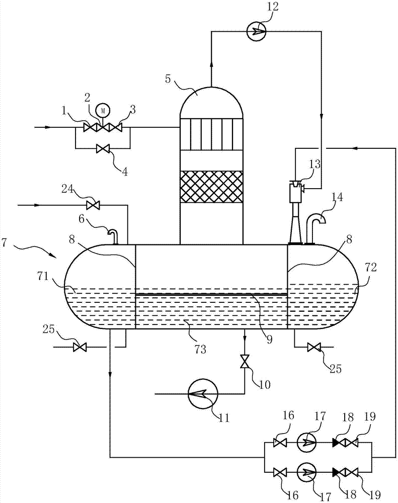
[0020] Such as figure 1 As shown, a regenerative vacuum deaerator, including

[0021] Deoxygenation head 5 adopts the structure in the prior art, and this deoxygenation head 5 comprises the water inlet that is located at the top of deoxygenation head 5 and is connected with the water inlet pipe and the exhaust port that is located at the top of deoxygenation head 5;

[0022] The water tank 7 is connected to the bottom of the deaeration head 5, and the water tank 7 is provided with two spacers 8 to separate the inner chamber of the water tank 7 into a front overflow tank 71, a rear overflow tank 72, and a tank between the front and rear overflow tanks and connected to the deaeration tank. The middle water tank 73 connected to the head 5 is provided with a heat-regenerating heat exchange pipe 9 that can communicate with the front and rear overflow water tanks. The front and rear overflow water tanks 71, 72 and the heat-regeneration heat exchange pipe 9 constitute a heat exchange...

Embodiment 2

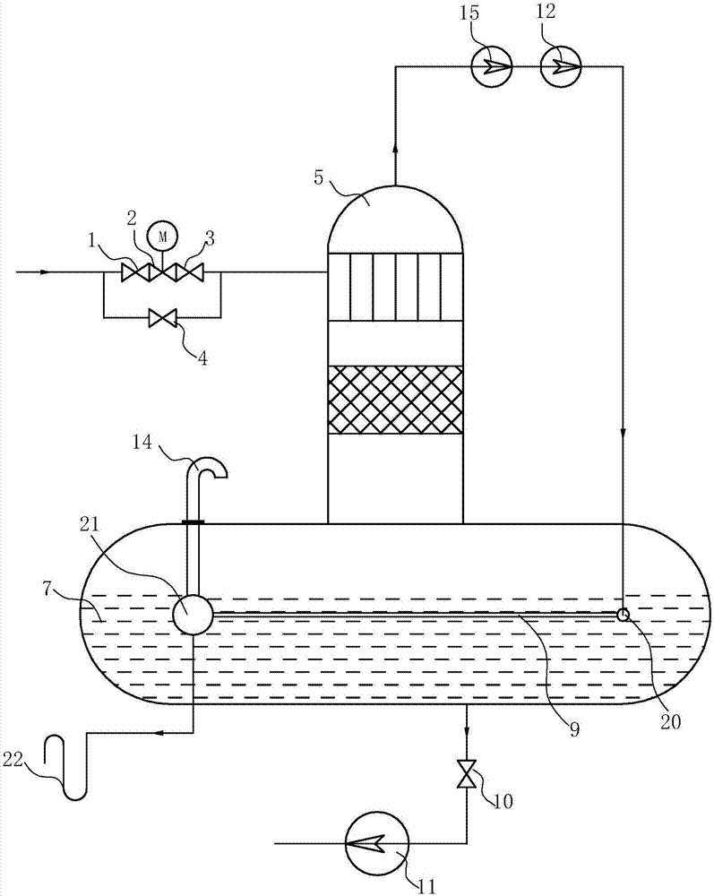
[0031] Such as figure 2 As shown, its structure is roughly the same as that of Embodiment 1, the difference is that the fore-stage vacuum pump of this embodiment adopts screw vacuum pump 12, and the main pump adopts Roots vacuum pump 15, so no working water system is required; The header 20, the gas-water separator 21 and the regenerative heat exchange pipe 9 connected to the exhaust heat recovery header 20 and the gas-water separator 21, the exhaust gas recovery header 20, the gas-water separator 21 and the heat recovery heat exchanger The tube 9 constitutes a heat exchange device, the outlet of the fore-stage vacuum pump is connected to the exhaust heat recovery tank 20, the top of the gas-water separator 21 is provided with an oxygen exhaust pipe 14 exposed to the water tank, and the bottom of the gas-water separator 21 is also It is connected with the steam trap 22 outside the water tank 7 through a pipeline.

[0032] The main process of this embodiment is:

[0033] 1. ...

Embodiment 3

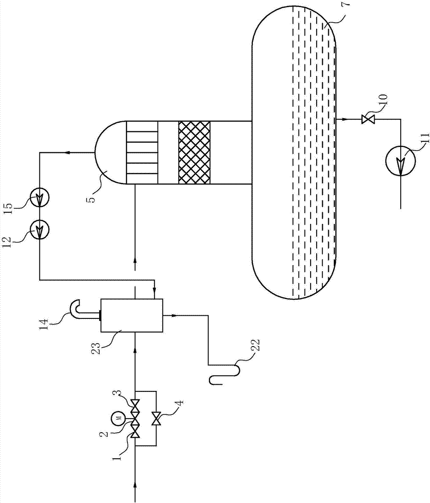
[0036] Such as image 3 As shown, its structure is roughly the same as that of Embodiment 2, the difference is that the heat exchange device of this embodiment is arranged outside the water tank, the heat exchange device is a heat exchanger 23, and the first inlet and the first outlet of the heat exchanger 23 are installed in series. In the water inlet pipe, the second inlet of the heat exchanger 23 is connected to the outlet of the backing vacuum pump (screw vacuum pump 12), and the second outlet of the heat exchanger 23 is connected to the steam trap 22, so as to exchange heat between the gas-vapor mixture and the feed water. Increase feed water temperature.

[0037] The main process of this embodiment is:

[0038] 1. Water supply process: During normal operation, the water supply enters the heat exchanger 23 through the isolation valve 1 before the water inlet regulating valve, the water inlet regulating valve 2, and the rear isolation valve 3 of the water inlet regulating...


PUM


Abstract

The invention relates to a heat regeneration type vacuum deaerator. The heat regeneration type vacuum deaerator comprises a deoxidization head connected with a water inlet pipe, and a water tank connected to the bottom of the deoxidization head and provided with a deoxidized water outlet. A steam exhaust port in the upper portion of the deoxidization head is connected with a vacuum pump through an exhaust pipe. The heat regeneration type vacuum deaerator is characterized by further comprising a heat exchange device arranged in the water tank or at the position of the water inlet pipe and used for heating water in the water tank or water at the position of the water inlet pipe. An outlet of the vacuum pump is connected with an inlet of the heat exchange device through a pipeline. Compared with the prior art, the heat regeneration type vacuum deaerator has the beneficial effects that a gas-steam mixture pumped through the vacuum pump can exchange heat with deoxidized water in the water tank or fed water in the water inlet pipe through the heat exchange device, the temperature of the deoxidized water in the water tank or the fed water in the water inlet pipe is increased, and the deoxidization efficiency is further improved while energy is saved. Thus, the satisfying deoxidization effect can be achieved without heating the fed water through additionally arrangement of a heat source, energy is saved, and the beneficial effects of reliable running and convenient control and operation are achieved.

Description

technical field [0001] The invention belongs to the field of boiler feed water treatment equipment, in particular to a regenerative vacuum deaerator. Background technique [0002] In the boiler feed water treatment process, oxygen removal is a very critical link. If oxygen is dissolved in the boiler feed water, the oxygen will corrode the feed water system and components of the boiler, and the corrosive substances entering the boiler will have adverse effects on the equipment and pipelines. Therefore, before the feed water enters the boiler, it needs to go through a deaerator to remove the oxygen in the water. At present, deaerators are divided into two categories: thermal deaerators and chemical (including electrochemical) deaerators. Thermal deaerators are further divided into three categories: vacuum deaerators, atmospheric deaerators and high-pressure deaerators. At present, most thermal deaerators need to input an external heat source (steam, flue gas or electric heati...

Claims


Application Information

Patent Timeline
Patent Type & Authority Applications(China)
IPC IPC(8): F22D1/50
CPCF22D1/50
Inventor 张少波钟立青陈志浩姚青青孙浩益
Owner 宁波健益检测科技有限公司
Why Eureka
Try Eureka