The method of laying holes in the second section of low-voltage anode aluminum foil

A technology of anode aluminum foil and hole layout, which is applied in the direction of electrolytic capacitors, capacitors, electrical components, etc., can solve the problems of small hole merging, low surface utilization rate, and product specific volume deviation, so as to improve density and size uniformity and avoid ratio The effect of volume reduction and uniform hole distribution

Active Publication Date: 2019-01-11
乳源县立东电子科技有限公司
View PDF9 Cites 0 Cited by
  • Summary
  • Abstract
  • Description
  • Claims
  • Application Information

AI Technical Summary

Problems solved by technology

Due to the influence of specific corrosion process parameters and the surface state of the aluminum foil, in many practical low-pressure aluminum foil microscopic corrosion structures, the size of the corrosion pits will be uneven, resulting in defects such as specific volume deviation, low strength, and low specific volume. High-end Technical manufacturers often use the lowest corrosion amount to obtain the highest specific volume and strength products. To achieve this, the size and distribution of corrosion holes are required to be uniform, and there are no joint holes and large pits. Therefore, the hole layout in the front section is necessary to determine the uniformity. Conditions, not only uniform holes must be distributed, but also the size of the holes is also required. If the size of the corrosion holes is too large, the specific surface utilization rate will be low and the specific volume will be low.
If the current density is too small, the corrosion holes will be too small, which will easily cause the merging of small holes in the multi-stage AC corrosion process, which is also not conducive to increasing the specific volume.
At present, all manufacturers adopt the technology of a section of holes, which is often not ideal due to the strength of the pre-treatment and the defects of the original surface of the aluminum foil.
Manufacturers with imperfect craftsmanship can't even control the size of the holes reasonably

Method used


Image

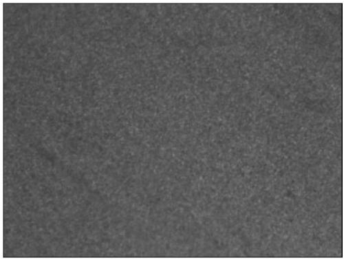
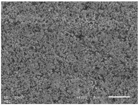
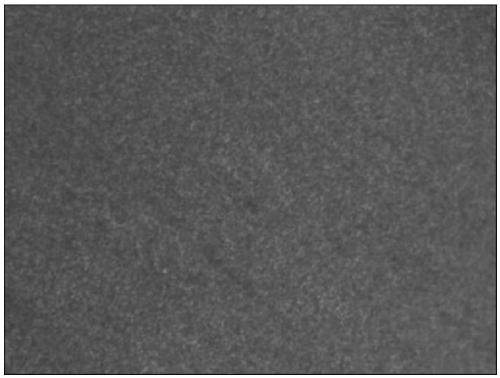
  • The method of laying holes in the second section of low-voltage anode aluminum foil
  • The method of laying holes in the second section of low-voltage anode aluminum foil
  • The method of laying holes in the second section of low-voltage anode aluminum foil

Examples


Embodiment 1

[0038] The method for distributing holes in the second section of the low-voltage anode aluminum foil described in this embodiment comprises the following steps:

[0039] S1: Put the pretreated and degreased aluminum foil in the mixed solution A of hydrochloric acid and sulfuric acid at a temperature of 40°C, and apply a current density of 0.3-0.7A / cm 2 , frequency f 1 Make surface holes for 25Hz alternating current, hole time t 1 For 40 seconds, after the hole-making process is completed, a section of hole-making aluminum foil is obtained;

[0040] S2: Put the piece of perforated aluminum foil obtained in S1 in the mixed solution B of hydrochloric acid and sulfuric acid at a temperature of 55°C, and apply a current density of 0.3-0.7A / cm 2 , frequency f 2 Supplementary hole layout for 25Hz alternating current, hole layout time t 2 for 20 seconds.

Embodiment 2

[0042] The method for distributing holes in the second section of the low-voltage anode aluminum foil described in this embodiment comprises the following steps:

[0043] S1: Put the pretreated and degreased aluminum foil in the mixed solution A of hydrochloric acid and sulfuric acid at a temperature of 40°C, and apply a current density of 0.3-0.7A / cm 2 , frequency f1 Make surface holes for 25Hz alternating current, hole time t 1 For 40 seconds, after the hole-making process is completed, a section of hole-making aluminum foil is obtained;

[0044] S2: Put the piece of perforated aluminum foil obtained in S1 in the mixed solution B of hydrochloric acid and sulfuric acid at a temperature of 55°C, and apply a current density of 0.3-0.7A / cm 2 , frequency f 2 Supplementary hole layout for 35Hz alternating current, hole layout time t 2 for 20 seconds.


PUM


Abstract

The invention relates to a method of second stage hole arrangement on a low voltage anode aluminum foil. The method of second stage hole arrangement on the low voltage anode aluminum foil comprises the following steps that S1, the aluminum foil is placed in a mixed solution A which is mixed by hydrochloric acid and vitriol, surface hole arrangement is conducted by exerting alternating current, and a first stage hole arranged aluminum foil is obtained; and S2, the first stage hole arranged aluminum foil is placed in a mixed solution B which is mixed by hydrochloric acid and vitriol, replenishing hole arrangement is conducted by exerting alternating current, specifically, the frequency of the alternating current in the step S1 is lower than that of the alternating current in the step S2. Compared with the prior art, the method of second stage hole arrangement on the low voltage anode aluminum foil can avoid excessive hole arrangement once, through the second stage hole arrangement, the uniformity of the hole arrangement can be improved, subsequent corrosion depth surface state is ensured to be consistent, and the specific volume of the anode aluminum foil in a certain voltage section can be effectively improved.

Description

technical field [0001] The invention relates to a method for manufacturing an anode aluminum foil for an aluminum electrolytic capacitor, in particular to a method for distributing holes in two sections of the low-voltage anode aluminum foil. Background technique [0002] Aluminum electrolytic capacitor is an energy storage element widely used in the electronic and electrical industry, and anode aluminum foil is an important raw material for aluminum electrolytic capacitors. The structural characteristics of anode aluminum foil determine the electrical performance of aluminum electrolytic capacitors. [0003] The electrolytic corrosion process of low-voltage anode aluminum foil is generally as follows: aluminum foil→pretreatment→first-level hole layout stage→multi-stage deep corrosion→cleaning and dechlorination treatment→stabilization treatment→sintering and drying. The main function of the pretreatment is to remove the oil, impurities and oxide film on the surface of the l...

Claims


Application Information

Patent Timeline
Patent Type & Authority Patents(China)
IPC IPC(8): C25F3/04C25F3/14C23F1/20C23F1/02H01G9/055
CPCC23F1/02C23F1/20C25F3/04C25F3/14H01G9/055
Inventor 冉亮杨海亮刘俊英
Owner 乳源县立东电子科技有限公司
Why Eureka
Try Eureka