Laser impacting strengthening method for small-hole components different in thickness

A technology of laser shock strengthening and laser shock, which is applied in the direction of laser welding equipment, manufacturing tools, welding/welding/cutting items, etc., can solve the problems of small hole damage, affecting the surface quality of hole precision and hole wall, and achieve good deformation and improvement Scientific and effective in ensuring the quality of the hole wall

Active Publication Date: 2017-10-20
JIANGSU UNIV
View PDF5 Cites 9 Cited by
  • Summary
  • Abstract
  • Description
  • Claims
  • Application Information

AI Technical Summary

Problems solved by technology

Compared with mechanical shot peening, this method is not limited by the size of the hole, and can make the strengthening layer uniform. However, because the hole is opened first and then strengthened, the laser will cause certain damage to the small hole, thereby affecting the accuracy of the hole and the rigidity of the hole wall. Surface Quality

Method used


Image

  • Laser impacting strengthening method for small-hole components different in thickness
  • Laser impacting strengthening method for small-hole components different in thickness
  • Laser impacting strengthening method for small-hole components different in thickness

Examples


Embodiment 1

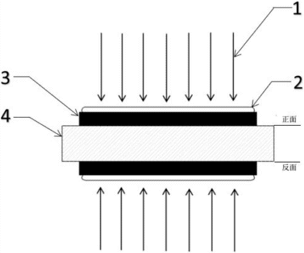
[0034] In this example, the material used is 7050-T7451 aluminum alloy sheet material, the thickness is 3mm, 4mm, 5mm, 6mm, and the hole diameter to be opened is 2.6mm. Such as figure 1As shown, the surface of the small hole component 4 is first pretreated, and then aluminum foil is pasted on the surface of the component to be opened as the energy absorbing layer 3, and water is used as the constraining layer 2 to make the water flow through the surface of the aluminum foil at a constant speed. The small-hole component 4 is fixed on the numerical control workbench with a fixture, and the running path of the numerical control workbench is programmed so that the laser can just strengthen the part of the component to be drilled. According to the selected constrained layer 2 is water, the absorption layer 3 is aluminum foil, according to P>2σ s , It can be seen that k=1, σ s =441Mpa, I 0 Should be greater than the lower limit of 0.78GW / cm 2 .

[0035] empirical formula B=...

example 2

[0040] The difference between this example and Example 1 is that the material used in this example is TC4-DT titanium alloy sheet material with a thickness of 3mm, 4mm, and 6mm, and the hole size to be opened is 2.6mm. The surface of the small-hole component 4 is first pretreated, and then the aluminum foil 3 is pasted on the surface of the component with openings as an energy absorption layer, and water 2 is used as a constraining layer to make the water flow through the surface of the aluminum foil at a uniform speed. Fix the component on the CNC workbench with a fixture, and program the running path of the CNC workbench so that the laser can just strengthen the part to be drilled. According to the selected constrained layer and absorbing layer, according to P>2σ s , It can be seen that k=1, σ s =811Mpa, I 0 Should be greater than the lower limit of 2.63GW / cm 2 .

[0041] empirical formula B=2.6, considering the stiffness and surface hardness of titanium alloy compre...

example 3

[0045] The difference between this example and Example 1 is that the material used in this example is 2024-T62 aluminum alloy sheet, the thickness is 2.5mm and 5mm, and the size of the holes to be opened is 2mm. Such as figure 1 As shown, the surface of the small hole member 4 is pretreated first, and then aluminum foil is pasted on the surface of the member with openings as the energy absorbing layer 3, and 4.5 mm thick K9 glass is used as the constraining layer 2. The component 4 is fixed on the CNC workbench with a fixture, and the running path of the CNC workbench is programmed so that the laser can just strengthen the part of the material to be drilled. According to the selected constrained layer and absorbing layer, according to P>2σ s , It can be seen that k=1.62, σ s =340Mpa, I 0 Should be greater than 0.18GW / cm 2 .

[0046] empirical formula B=6, A is about 4.8, and the laser power density of the small hole component 4 with a thickness of 2.5mm can be 1.57GW / ...


PUM

PropertyMeasurementUnit
laser pulse widthaaaaaaaaaa
diameteraaaaaaaaaa
thicknessaaaaaaaaaa

Abstract

The invention provides a laser impacting strengthening method for small-hole components different in thickness. In the method, different technology parameters are adopted for laser impacting strengthening of the small-hole components different in thickness, the statistics analysis is conducted after a large number of tests, the empirical formula is obtained, the empirical formula is the relation of the power intensity and small-hole component thickness and is shown in the specification, the power density of laser impacting strengthening of the small-hole components different in thickness can be determined according to the relation, and a related technology parameter selecting and determining method is provided. According to the method, after the small-hole components different in thickness are subjected to laser impacting strengthening through the proper technology, reasonable residual compressive stress distribution can be obtained, a good strengthening effect is achieved, and effective impact quality control can be conducted on the components; and on the premise that the fatigue life of the small-hole components is guaranteed, workpiece deformation is controlled.

Description

technical field [0001] The invention relates to the field of laser processing, in particular to a small-hole component with different thicknesses that uses different laser parameters for laser shock strengthening of small-hole components with different thicknesses, so that the strengthening effect of small-hole holes with different plate thicknesses can reach a good state. Laser shock peening method. Background technique [0002] Small hole components are typical stress concentration details, which are prone to fatigue cracks under fatigue loads, affecting the performance and service life of key structures. And many mechanical parts need to be drilled, especially the parts on the aircraft need to drill thousands of holes, these holes become the weak link of the parts, and these parts have different thicknesses. Traditional mechanical strengthening methods such as mechanical shot peening and extrusion strengthening are limited by the hole diameter, and it is not easy to stre...

Claims


Application Information

Patent Timeline
Patent Type & Authority Applications(China)
IPC IPC(8): C21D10/00
CPCC21D10/005C21D2221/00B23K26/356B23K2103/10
Inventor 姜银方李旭赵勇姜文帆华程季彬朱恒孟李林
Owner JIANGSU UNIV
Why Eureka
Try Eureka