Super-surface lens antenna

A lens antenna and metasurface technology, applied in antennas, electrical components, circuits, etc., can solve the problems of complex structure, poor standing wave ratio, and large volume, and achieve the effect of small volume, small standing wave ratio, and high gain

Active Publication Date: 2017-10-20
AIR FORCE UNIV PLA
View PDF4 Cites 17 Cited by
  • Summary
  • Abstract
  • Description
  • Claims
  • Application Information

AI Technical Summary

Problems solved by technology

However, the metamaterial unit structure that constitutes these lenses is often a three-dimensional block structure, which still has the defects of large volume, heavy weight, complex structure, and poor standing wave ratio.

Method used


Image

  • Super-surface lens antenna
  • Super-surface lens antenna
  • Super-surface lens antenna

Examples


Embodiment Construction

[0024] The technical solutions in the embodiments of the present invention will be clearly and completely described below in conjunction with the accompanying drawings in the embodiments of the present invention. Apparently, the described embodiments are only some of the embodiments of the present invention, not all of them. Based on the embodiments of the present invention, all other embodiments obtained by persons of ordinary skill in the art without making creative efforts all belong to the protection scope of the present invention.

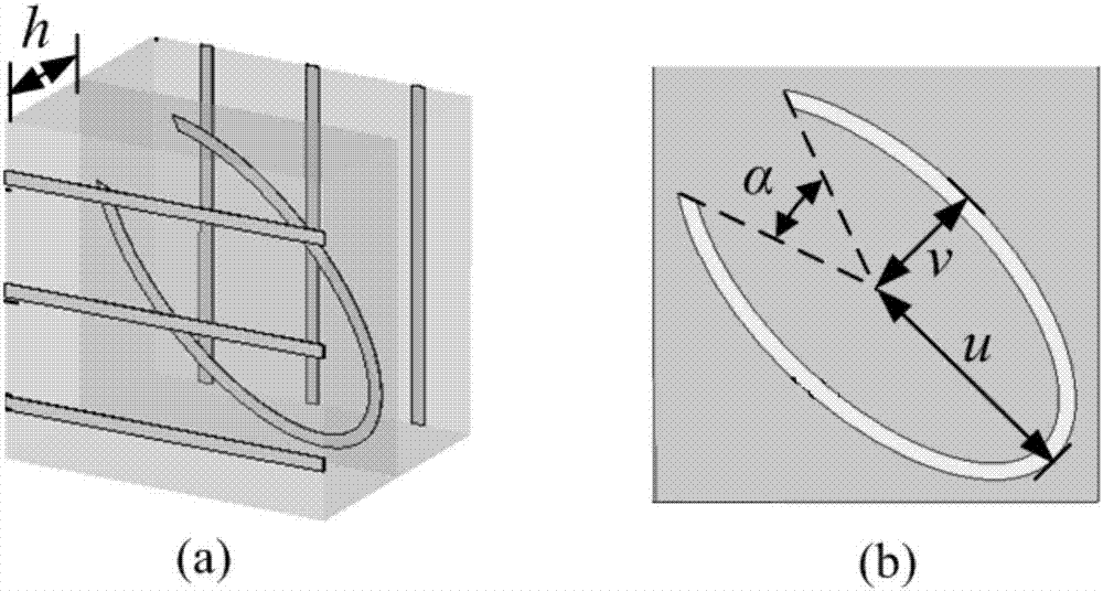
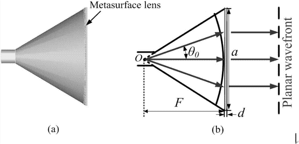
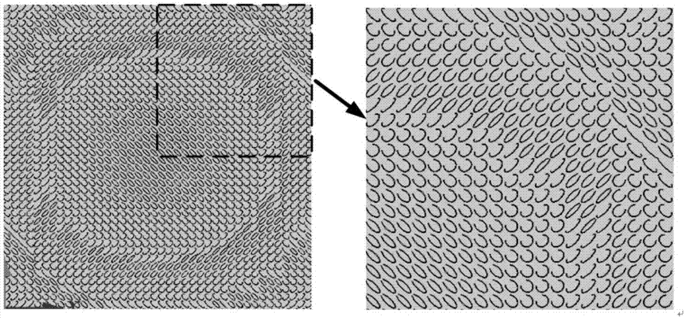
[0025] The metasurface lens antenna of the present invention is a novel lens antenna based on beam-focusing metasurface loading. The antenna is realized by loading an ultra-thin transmissive beam-focusing metasurface on the aperture surface of a conical horn antenna. The transmissive beam-focusing metasurface is composed of It is composed of a plurality of transmissive linear polarization conversion unit structures. figure 1 It is a structural...


PUM


Abstract

The invention discloses a super-surface lens antenna, and belongs to the technical field of antennas. The antenna consists of a conical-horn antenna and a wave beam focusing super-surface with the sub-wavelength thickness. The wave beam focusing super-surface is formed by a transmission-type linear polarization unit structure array with the parabolic-type cross polarization phase space distribution. The transmission-type linear polarization unit structure sequentially comprises a metal grid, a dielectric substrate, a metal elliptical opening resonant ring, a dielectric substrate and a metal grid from the bottom to the top. The size and period of the transmission-type linear polarization unit structure can change the working frequency band, bandwidth and the focusing efficiency of the wave beam focusing super-surface. According to the invention, the core component, the wave beam focusing super-surface, of the super-surface lens antenna is manufactured through the printed circuit board technology. The super-surface lens antenna is low in construction cost, employs a plane structure, has the sub-wavelength thickness, is light in weight, is small in size, is small in standing-wave ratio, is narrow in beam, is high in gain, and can be designed and implemented at any band.

Description

technical field [0001] The invention relates to the technical field of antennas, in particular to a lens antenna based on a metasurface plane lens. Background technique [0002] A lens antenna is an antenna that can convert a point source or line source spherical wave or cylindrical wave into a plane wave through electromagnetic waves to obtain a pencil-shaped, fan-shaped or other shaped beam. It is widely used in microwave relay communication. By rationally designing the shape of the lens surface and the refractive index n, the phase velocity of the electromagnetic wave is adjusted to obtain a plane wavefront on the radiation aperture. Lenses can be made of natural media (n>1), or artificial media (n>1 or n<1) made of metal mesh or metal plate. Traditional lens antennas, such as non-metallic dielectric lens antennas, artificial dielectric lens antennas, H-plane metal plate lens antennas, E-plane metal plate lens antennas, etc., generally have curved lenses, which...

Claims


Application Information

Patent Timeline
Patent Type & Authority Applications(China)
IPC IPC(8): H01Q19/08H01Q15/02H01Q15/24H01Q13/02
CPCH01Q13/02H01Q15/02H01Q15/242H01Q19/08
Inventor 李勇峰屈绍波韩亚娟张介秋陈红雅王甲富
Owner AIR FORCE UNIV PLA
Why Eureka
Try Eureka