
Porous metal rod

A porous metal and round rod technology, which is applied in the field of porous metal rods for medical implants, can solve the problems of poor bone tissue growth at the front end of the porous tantalum rod, affecting the treatment effect, and fracture, so as to improve the success rate of treatment and facilitate installation , to avoid the effect of fracture failure

Active Publication Date: 2017-10-31
CHONGQING RUNZE PHARM CO LTD
View PDF4 Cites 2 Cited by
  • Summary
  • Abstract
  • Description
  • Claims
  • Application Information

AI Technical Summary

Problems solved by technology

[0007] Since the stress on the femoral head is irregular and the direction of the resultant force is at an angle to the direction of the center of gravity of the body, it is more likely to cause stress concentration. The above-mentioned porous tantalum metal rod breaks during use
Moreover, there is also a phenomenon that the bone tissue at the front end of the porous tantalum rod does not grow into it well, thus affecting the therapeutic effect

Method used


Image

  • Porous metal rod
  • Porous metal rod
  • Porous metal rod

Examples


Embodiment 1

[0032] Mix polyvinyl alcohol, distilled water, and tantalum powder with an average particle size of less than 5 microns and an oxygen content of less than 0.1% according to the weight ratio of 7:125:150 to make a slurry. The average pore size is 0.6mm and the density is 0.022g / cm 3 The porous polyurethane foam is put into the slurry, so that the pores of the polyurethane foam are filled with the tantalum powder slurry, and the polyurethane foam is dried in a vacuum oven at a drying temperature of 60°C, for a drying time of 10 hours, and a vacuum of 1Pa. Then pass the vacuum below 10 -4 Pa, temperature 600°C, heat preservation time 120 minutes for degreasing treatment, and then vacuum sintering, sintering temperature 2100°C, heat preservation 2 hours, vacuum degree 10 -4 Pa, the sintering process is filled with hydrogen protection. The porosity of the prepared porous tantalum is 50%, and the pore size is 100µm-310µm. This material is machined to produce the desired porous t...

Embodiment 2

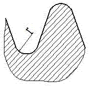
[0035] This embodiment is similar to Embodiment 1, except that the porosity of porous tantalum is 85%, the pore size is 300µm-500µm, the length of the reduced part of the thread is 50% of the length of the thread part, and the radius of the fillet at the root of the thread is 0.65mm .

Embodiment 3

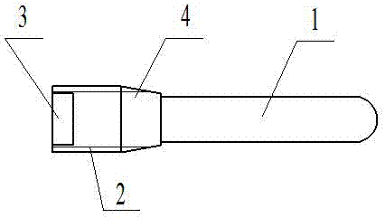
[0037]This example is similar to example 1, with reference to the preparation method of example 1, the difference is that metal niobium is used to prepare, the root diameter of the threaded part is 1.2 times the diameter of the round bar-shaped part, and the root diameter of the threaded part is close to the round bar-shaped part It gradually decreases towards the round rod-shaped part, until the junction of the threaded part and the round rod-shaped part decreases to 1.05 times the diameter of the round rod-shaped part, and the length of the root diameter of the threaded part close to the round rod-shaped part gradually decreases towards the round rod-shaped part. 20% of the length.


PUM

PropertyMeasurementUnit
radiusaaaaaaaaaa
diameteraaaaaaaaaa
pore sizeaaaaaaaaaa

Abstract

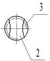
The invention relates to a porous metal rod for medical implanting used for treating early-stage and middle-stage femoral head necrosis. The porous metal rod comprises two parts, wherein one part is a round-rod-shaped part, the other part connected with the round-rod-shaped part is a threaded part, threads are arranged on the outer part of the threaded part, the outer diameter of the threads is greater than that of the round rod shape, a notch is formed in the end face of the threaded part, the outer diameter of one section, close to the round rod shape, of the threaded part is gradually reduced towards the round-rod-shaped part, so that the stress at the joint of the threaded part and the round-rod-shaped part is reduced, thus the fracture failure of the porous metal rod can be avoided, and finally, the treatment success rate is improved.

Description

technical field [0001] The invention relates to the field of prostheses, in particular to a medically implanted porous metal rod for treating early and mid-term necrosis of the femoral head. Background technique [0002] Femoral head necrosis is a pathological process in which the blood supply of the femoral head is destroyed and the degeneration of bone cells leads to the death of the active components of the bone caused by various reasons. The main clinical symptoms in the early stage are chronic pain of the hip joint on the affected side, activity dysfunction and progressive claudication. Pain is one of the common clinical diseases. In my country, the number of people with necrosis of the femoral head is very large. It often occurs in young adults aged 30-50. Most of them are male. Most patients need total hip replacement, which will not only seriously affect their personal life and work, but also directly or indirectly bring a heavy burden to their families and society....

Claims


Application Information

Patent Timeline
Patent Type & Authority Applications(China)
IPC IPC(8): A61F2/28A61F2/36A61L27/56A61L27/06A61L27/04
CPCA61F2/28A61F2/3609A61F2002/2828A61F2002/30011A61F2002/30224A61F2002/30593A61F2002/30683A61F2002/30968A61F2002/3611A61F2002/3621A61F2310/00017A61F2310/00023A61F2310/00029A61F2310/00095A61F2310/00131A61L27/042A61L27/045A61L27/047A61L27/06A61L27/56A61L2430/02
Inventor 叶雷
Owner CHONGQING RUNZE PHARM CO LTD
Learn More