Working method capable of lowering outage rate during electrical equipment overhaul
A technology of electric equipment and working methods, applied in the direction of separation methods, chemical instruments and methods, substation/power distribution device shells, etc., can solve the problems of non-stop work and gradual recovery of particles, and achieve efficient recovery, Enhance efficiency and avoid pollution effect
- Summary
- Abstract
- Description
- Claims
- Application Information
AI Technical Summary
Problems solved by technology
Method used
Image
Examples
Embodiment 1
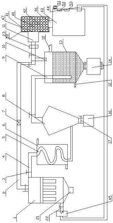
[0044] A dust removal device for reducing the power failure rate of electric equipment maintenance, comprising a first dust removal mechanism, a power conversion mechanism connected to the first end of the first dust removal mechanism, and a first dust removal mechanism connected to the second end of the first dust removal mechanism. The regeneration mechanism, the settling mechanism connected with the energy conversion mechanism, the dust accumulation module arranged at the lower part of the settling mechanism, the absorbing mechanism arranged at the rear of the settling mechanism, and the discharge mechanism 11 arranged at the upper part of the absorbing mechanism , a circulation mechanism connected with the absorption mechanism, a discharge module arranged at the lower part of the absorption mechanism, and an adsorption filter mechanism 23 arranged between the absorption mechanism and the discharge mechanism;
[0045] The first dust removal mechanism includes a plurality of ...
Embodiment 2
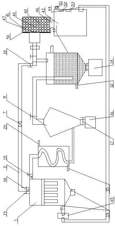
[0056] Embodiment 2, which is different from Embodiment 1 in that: the regeneration pipeline 2, the regeneration discharge pipe 21, and the first air intake pipe 22 are all equipped with a detection module 19;
[0057] The detection module 19 includes a flow rate sensor 192 , a dust sensor 191 and a temperature sensor 193 .
[0058] The first regeneration mechanism adopted in this embodiment includes a regeneration pipeline communicated with the discharge mechanism, solenoid valves arranged at both ends of the regeneration pipeline, a regeneration supercharger arranged in the middle of the regeneration pipeline, and a The regeneration discharge pipe at the lower part of the dust collector; the airflow can be pressurized by the regeneration supercharger to ensure that there is a high-speed airflow to clean the dust collector during back-blowing and dust removal, which can greatly reduce the amount of back-blowing gas and ensure The effect of overall cleaning; the energy convers...
Embodiment 3
[0059] Embodiment 3: The difference between it and Embodiment 2 is that: the first dust removal mechanism, the energy conversion mechanism, the first regeneration mechanism, the sedimentation mechanism, the dust accumulation module, the absorption mechanism, the discharge mechanism, the circulation mechanism, and the unloading module are all compatible with The signal interconnection of the control modules arranged on the outer wall of the dust collector;
[0060] The control module is PLC or personal computer.
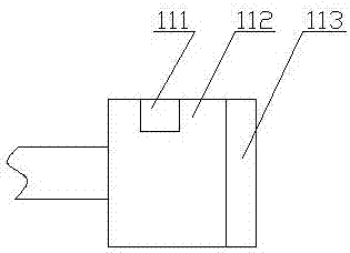
[0061] The adsorption turntable includes two ring-shaped sealing plates 231, a cylindrical channel 232 that is arranged between the two ring-shaped sealing plates 231 and matches the discharge pipe, and connects the mandrel 237 with the ring. A plurality of support arms 233 between the shaped sealing plates 231;
[0062] The adsorption module is arranged in the cylindrical channel 232, and the sealing ring 235 matched with the annular sealing plate 231 is arranged on...
PUM
 Abstract
Description
Claims
Application Information
 - R&D
- Intellectual Property
- Life Sciences
- Materials
- Tech Scout
- Unparalleled Data Quality
- Higher Quality Content
- 60% Fewer Hallucinations
Browse by: Latest US Patents, China's latest patents, Technical Efficacy Thesaurus, Application Domain, Technology Topic, Popular Technical Reports.
© 2025 PatSnap. All rights reserved.Legal|Privacy policy|Modern Slavery Act Transparency Statement|Sitemap|About US| Contact US: help@patsnap.com


