

Continuous preparation method of perfluoropolyether
A technology of perfluoropolyether and fluorine gas is applied in the field of continuous preparation of perfluoropolyether, which can solve the problems of large amount of fluorine gas, high safety risk and long reaction time, etc.
- Summary
- Abstract
- Description
- Claims
- Application Information
AI Technical Summary
Problems solved by technology
Method used
Image

Examples
Embodiment 1
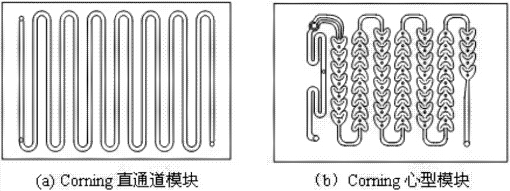
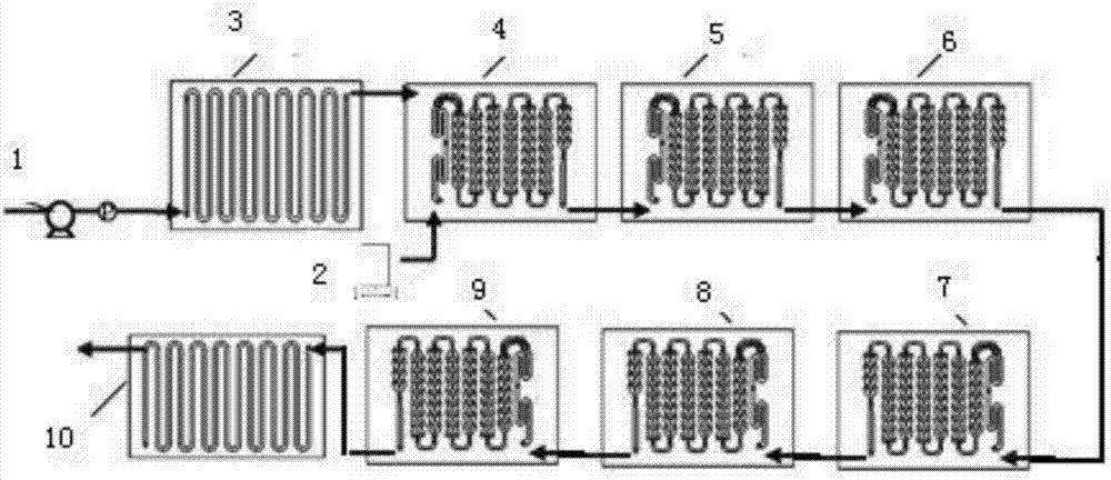
[0030] optional attachment figure 2 1 medium corning straight channel module (as a pre-mixing preheating module), 6 corning "heart-shaped" microchannel reaction modules, 1 corning straight channel module (as a quenching module) and 8 heat transfer modules, according to the attached image 3 The reaction process shown constitutes a continuous flow microchannel reaction system. Heat transfer oil is used as the reaction heat exchange medium. According to the forced heat transfer principle of the microchannel reactor, only two temperature measuring points are set at the reactor inlet and outlet. Before the reaction, the microchannel reaction system and connecting pipelines were dewatered and degreased respectively, and the system and connecting pipelines were passivated with fluorine gas using 5mol% fluorine-nitrogen mixed gas, and the air tightness inspection was carried out at 1.0MPa. by attaching image 3 The 1 liquid phase pump (such as diaphragm metering pump) in the system...
Embodiment 2
[0034] Use the same Corning microchannel reactor as in Example 1, and follow the same connection and control methods. In this example, the reaction conditions were changed.
[0035] Set the heat exchanger temperature to 70°C, that is, the reaction temperature, and set the reaction pressure to 0 MPa. Raw material CF 3 CF 2 CF 2 O(CF 2 CF(CF 3 )O) 52 CF(CF 3 )COOH (average weight-average molecular weight is about 8692), the feed rate is 16g / min, the feed rate of 20mol% fluorine-nitrogen mixed gas is 2.7g / min, and the molar ratio of fluorine gas to raw materials is 8:1. The reaction raw materials enter the "heart-shaped" micro-channel reaction module 4 after passing through the micro-channel premixing and preheating module 3, and the mixed gas of fluorine and nitrogen directly enters the "heart-shaped" micro-channel reaction module 4 through the gas mass flow meter, In the channel reaction module 4-9, the mixed gas of fluorine and nitrogen reacts with the raw materials. ...
Embodiment 3
[0037] Use the same Corning microchannel reactor as in Example 1, and follow the same connection and control methods. In this example, the reaction conditions were changed.
[0038] Set the heat exchanger temperature to 120°C, that is, the reaction temperature, and set the reaction pressure to 0 MPa. Raw material CF 3 CF 2 CF 2 O(CF 2 CF(CF 3 )O) 22 CF(CF 3 )COOH (average weight-average molecular weight is about 3982), the feed rate is 17g / min, the feed rate of 20mol% fluorine-nitrogen mixed gas is 1.7g / min, and the molar ratio of fluorine gas to raw materials is 2.1:1. The reaction raw materials enter the "heart-shaped" micro-channel reaction module 4 after passing through the micro-channel premixing and preheating module 3, and the mixed gas of fluorine and nitrogen directly enters the "heart-shaped" micro-channel reaction module 4 through the gas mass flow meter, In the channel reaction module 4-9, the mixed gas of fluorine and nitrogen reacts with the raw materials...
PUM
 Abstract
Description
Claims
Application Information