Method for regulating and controlling stable flow of liquid nitrogen jet flow state

A technology for stabilizing the flow rate and flow state, which is applied in the field of regulation and control of the stable flow rate of the liquid nitrogen jet state, and can solve the problem of not mentioning the regulation method of the stable flow rate of the liquid nitrogen jet state, not involving liquid nitrogen flow control, and insufficient cooling effect in the cutting area, etc. problem, to achieve stable liquid nitrogen jet state, compact structure, and reduce the effect of mass fraction

Inactive Publication Date: 2017-11-24
DALIAN UNIV OF TECH
View PDF7 Cites 7 Cited by
  • Summary
  • Abstract
  • Description
  • Claims
  • Application Information

AI Technical Summary

Problems solved by technology

In 2013, Shanghai Aerospace Equipment Manufacturing General Factory disclosed "a low-temperature nitrogen gas supply system for low-temperature processing" in the invention patent CN201320088413.0. The PLC controller regulates the low-temperature nitrogen jet flow, but the gas mass fraction of the two-phase flow is too large, and the cooling effect of the low-temperature medium on the cutting area during processing is insufficient
In 2016, Zhang Xiaoming and others disclosed "a double-nozzle liquid nitrogen cooling system suitable for Inconel718 cutting processing" in the invention patent CN105583689A. Nitrogen Flow Control Problems
[0004] However, none of the above methods considered the influence of the gas mass fraction of the two-phase flow on the liquid nitrogen delivery state, and did not mention the regulation method of the steady flow rate of the liquid nitrogen jet state

Method used


Image

  • Method for regulating and controlling stable flow of liquid nitrogen jet flow state
  • Method for regulating and controlling stable flow of liquid nitrogen jet flow state

Examples


specific Embodiment approach

[0019] The thermal conductivity of the vacuum insulated pipe adopted in the embodiment is 2×10 -5 W / (m·K), the temperature difference between the inner and outer walls can withstand up to 270 degrees; the nominal pressure of the self-pressurized Dewar tank is 1.4Mpa.

[0020] The specific steps of the method are as follows:

[0021] The first step is to assemble the liquid nitrogen delivery device

[0022] The liquid nitrogen delivery device consists of a liquid nitrogen delivery pipeline system and a liquid nitrogen flow control unit.

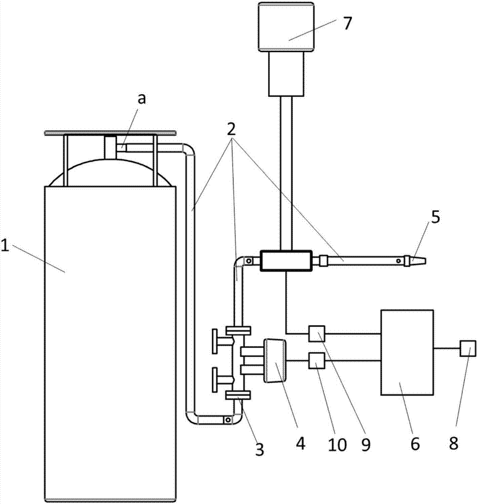
[0023] Assemble the liquid nitrogen delivery pipeline system first, such as figure 1 shown. The system consists of a self-pressurized Dewar tank 1, a vacuum insulation tube 2, a flange 3, a liquid nitrogen flow meter 4, a nozzle 5 and an ultra-low temperature regulating valve 7; The liquid port a is connected to the vacuum insulation pipe 2 through threads; the vacuum insulation pipe 2 is connected to the liquid nitrogen flowmeter 4 throug...


PUM


Abstract

The invention relates to a method for regulating and controlling the stable flow of the liquid nitrogen jet flow state and belongs to the field of cryogenic engineering. According to regulation of the stable flow of the liquid nitrogen jet flow state through the method, a heat insulation pipeline is utilized to reduce heat leakage, the two-phase flow gas mass fraction is regulated and controlled within a certain range, the gasification ratio of liquid nitrogen in the delivering process is decreased, and the stable output result in the allowable range is obtained. The liquid nitrogen delivering flow is monitored in real time, and liquid nitrogen flow regulation and stable output are achieved through a PID regulating and control method. According to the method, cryogenic fluids in cryogenic medium processing are effectively stabilized, regulated and controlled, the dry degree of the liquid nitrogen in pipeline delivering is decreased, and the utilization rate of the fluids during liquid nitrogen ultra-low temperature cutting is increased. A liquid nitrogen delivering device is compact in structure, a vacuum pipeline is adopted, the heat loss in the pipeline is reduced, the liquid nitrogen gasification rate is decreased, the two-phase flow gas mass fraction is decreased, the liquid nitrogen jet flow state is stabilized, and the liquid nitrogen flow is accurately regulated and controlled.

Description

technical field [0001] The invention belongs to the field of cryogenic engineering, and in particular relates to a method for regulating and controlling the stable flow rate of a liquid nitrogen jet. Background technique [0002] In recent years, liquid nitrogen has been widely used in the cooling of superconducting magnets, low-temperature minimally invasive surgery, ultra-low temperature cooling processing and other fields. In particular, using liquid nitrogen as the cooling medium to implement ultra-low temperature cooling processing has unique advantages in prolonging tool life, improving processing quality and processing efficiency, and is also beneficial to the low-temperature medium (two-phase nitrogen) flow rate delivered to the tool-workpiece interaction area. , gas mass fraction, etc. put forward extremely high requirements. The higher the content of liquid nitrogen, that is, the lower the gas mass fraction, the better the cooling and lubricating effect of the cry...

Claims


Application Information

Patent Timeline
Patent Type & Authority Applications(China)
IPC IPC(8): F17C7/02F17C13/02F17C13/00F17C13/04F17D1/00F17D1/08F17D3/01F17D3/18
CPCF17C7/02F17C13/002F17C13/02F17C13/04F17C2205/0323F17C2205/0352F17C2221/014F17C2223/013F17C2270/0509F17D1/005F17D1/082F17D3/01F17D3/18
Inventor 王永青刘海波王晋宇韩灵生袁凯袭萌萌郭立杰任斐郭东明
Owner DALIAN UNIV OF TECH
Why Eureka
Try Eureka