Eureka AIR delivers breakthrough ideas for toughest innovation challenges, trusted by R&D personnel around the world.

Water-based environment-friendly cleaning method and cleaning device of soldering flux on radar electronic module

A technology of electronic components and flux, which is applied in the field of automated radar electronic batch production, can solve problems such as high reliability requirements, hidden dangers to personnel safety, and general cleaning effect, so as to avoid secondary pollution, high-efficiency rinsing effect, and good cleaning effect Effect

Active Publication Date: 2017-12-01
CHINA ELECTRONIC TECH GRP CORP NO 38 RES INST
View PDF6 Cites 4 Cited by
  • Summary
  • Abstract
  • Description
  • Claims
  • Application Information

AI Technical Summary

Problems solved by technology

New materials represented by LTCC, aluminum nitride, aluminum silicon, aluminum silicon carbide, etc. are being more and more widely used in advanced radar electronic components. These new materials each have their own new characteristics: LTCC and aluminum nitride themselves belong to Porous material, rough surface is easy to absorb flux, and due to the brittleness of ceramics and other reasons, it cannot be simply cleaned with high-power ultrasonic vibration cleaning equipment
Aluminum-silicon, aluminum-silicon carbide, etc. are used as the box material, and the surface coating is difficult to achieve high flatness, and it is not easy to polish, and the probability of residual flux is high
Since radar electronics often have high requirements on reliability and cannot have excessive flux residues, it is a difficult problem to clean flux residues after the mass production of radar electronic components after assembly and welding
Solvent cleaning or gas phase cleaning is often used in the industry to dissolve the flux by using the high solubility of the solvent. This method uses a large amount of solvent. First, the environmental protection is poor, and second, there are potential safety hazards for personnel. In order to achieve a good cleaning effect at low temperature, it is forced to choose Highly non-polar solvents have a general cleaning effect on ionic pollutants

Method used


Image

  • Water-based environment-friendly cleaning method and cleaning device of soldering flux on radar electronic module
  • Water-based environment-friendly cleaning method and cleaning device of soldering flux on radar electronic module
  • Water-based environment-friendly cleaning method and cleaning device of soldering flux on radar electronic module

Examples


Embodiment 1

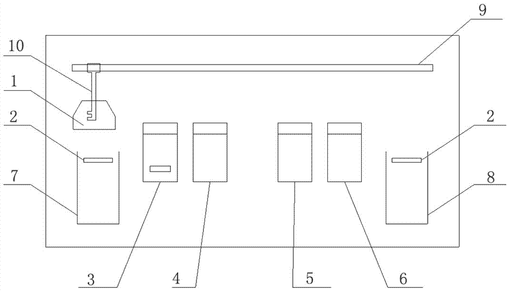
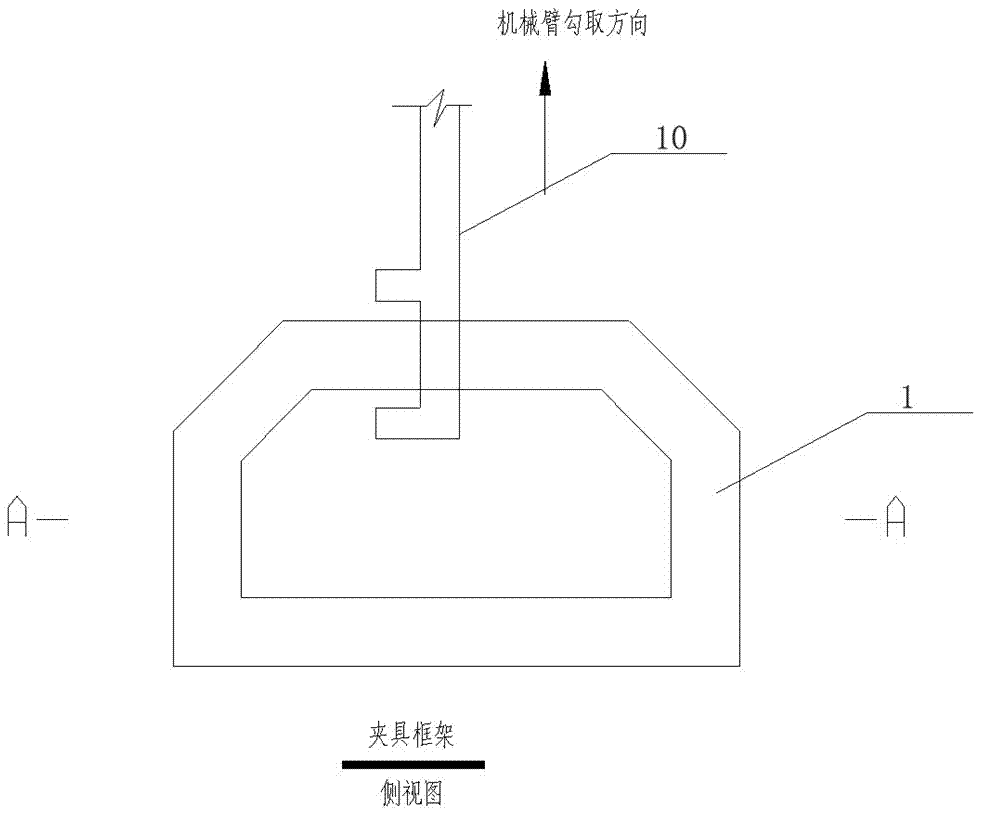
[0052] see figure 1 with Figure 9 , the cleaning device includes a cleaning fixture 1, a conveyor belt 2, a immersion ultrasonic jet cleaning mechanism 3, a reverse spray rinsing mechanism 4, a solvent dehydration bubbling mechanism 5, a drying mechanism 6, a loading table 7 and an unloading table 8, a mobile Mechanism 9 and suspension hook 10.

[0053] The cleaning object is the radar electronic components of the relevant connectors that have been assembled and welded.

[0054] The water-based environmental protection cleaning operation steps for the flux generated during the welding process of radar electronic components are as follows:

[0055] (1) Clamping the radar electronic components to be cleaned

[0056] Clamp and fix 100 radar electronic components A to be cleaned on the cleaning fixture 1, and send them to the loading table 7;

[0057] The arrangement spacing between adjacent radar electronic components to be cleaned is 5cm.

[0058] (2) soaking ultrasonic je...

Embodiment 2

[0070] see figure 1 with Figure 9 , the cleaning device includes a cleaning fixture 1, a conveyor belt 2, a immersion ultrasonic jet cleaning mechanism 3, a reverse spray rinsing mechanism 4, a solvent dehydration bubbling mechanism 5, a drying mechanism 6, a loading table 7 and an unloading table 8, a mobile Mechanism 9 and suspension hook 10.

[0071] The cleaning object is the radar electronic components of the relevant connectors that have been assembled and welded.

[0072] The water-based environmental protection cleaning operation steps for the flux generated during the welding process of radar electronic components are as follows:

[0073] (1) Clamping the radar electronic components to be cleaned

[0074] Clamp and fix 10 radar electronic components B to be cleaned on the cleaning fixture 1, and send them to the loading table 7;

[0075] The spacing between adjacent radar electronic components to be cleaned is 10cm.

[0076] (2) soaking ultrasonic jet cleaning ...

Embodiment 3

[0088] see figure 1 with Figure 9 , the cleaning device includes a cleaning fixture 1, a conveyor belt 2, a immersion ultrasonic jet cleaning mechanism 3, a reverse spray rinsing mechanism 4, a solvent dehydration bubbling mechanism 5, a drying mechanism 6, a loading table 7 and an unloading table 8, a mobile Mechanism 9 and suspension hook 10.

[0089] The cleaning object is the radar electronic components of the relevant connectors that have been assembled and welded.

[0090] The water-based environmental protection cleaning operation steps for the flux generated during the welding process of radar electronic components are as follows:

[0091] (1) Clamping the radar electronic components to be cleaned

[0092] Clamp and fix 25 radar electronic components C to be cleaned on the cleaning fixture 1, and send them to the loading table 7;

[0093] The arrangement spacing between adjacent radar electronic components to be cleaned is 8cm.

[0094] (2) soaking ultrasonic jet...


PUM


Abstract

The invention provides a water-based environment-friendly cleaning method of soldering flux generated in the welding process of a radar electronic module. The cleaned object is the radar electronic module of which a ceramic substrate and a related connector are installed and welded. A cleaning system comprises a cleaning clamp, a moving mechanism, a soaking ultrasonic flow spraying cleaning mechanism, a reverse spraying rinsing mechanism, a solvent dehydration bubbling mechanism, a baking mechanism and a feeding and discharging table. According to the operation steps, 1, the radar electronic module to be cleaned is clamped; 2, soaking ultrasonic flow spraying cleaning is carried out, and a multi-component composite water-based cleaning solution is adopted as a soaking cleaning solution; 3, pure water is used for carrying out reverse spraying rinsing; 4, solvent dehydration bubbling treatment is carried out, and dehydration solvent is ethyl alcohol with concentration being over 95% or other alcohol solutions easy to volatilize; and 5, hot wind baking is carried out.

Description

technical field [0001] The invention belongs to the field of automatic radar electronic batch production, and in particular relates to a method for cleaning flux produced in the welding process of radar electronic components. Background technique [0002] With the development trend of advanced radar electronic systems moving toward arrayization, the system side has begun to demand thousands of single systems for radar electronic components. In the face of huge demand for components and system requirements for component consistency, automated production has become the only way to cope. New materials represented by LTCC, aluminum nitride, aluminum silicon, aluminum silicon carbide, etc. are being more and more widely used in advanced radar electronic components. These new materials each have their own new characteristics: LTCC and aluminum nitride themselves belong to Porous material, rough surface is easy to absorb flux, and due to the brittleness of ceramics and other reaso...

Claims


Application Information

Patent Timeline
IPC IPC(8): B08B3/12B08B3/02B08B3/08F26B15/18F26B21/00
CPCB08B3/02B08B3/08B08B3/12F26B15/18F26B21/001F26B21/004
Inventor 林文海邱颖霞闵志先宣翔
Owner CHINA ELECTRONIC TECH GRP CORP NO 38 RES INST
Why Eureka
Eureka Blog
Learn More