Sewage treatment system and sewage treatment method

A sewage treatment system and sewage technology, applied in water/sewage treatment, light water/sewage treatment, neutralized water/sewage treatment, etc. Affect production efficiency and other problems, and achieve the effect of excellent treatment effect, high work efficiency and compact structure

Inactive Publication Date: 2017-12-01
ANYANG INST OF TECH
View PDF2 Cites 10 Cited by
  • Summary
  • Abstract
  • Description
  • Claims
  • Application Information

AI Technical Summary

Problems solved by technology

In addition, in the process of sewage treatment, most indicators can often be taken into account, but the treatment of a certain indicator is

Method used


Image

  • Sewage treatment system and sewage treatment method
  • Sewage treatment system and sewage treatment method

Examples


Embodiment 1

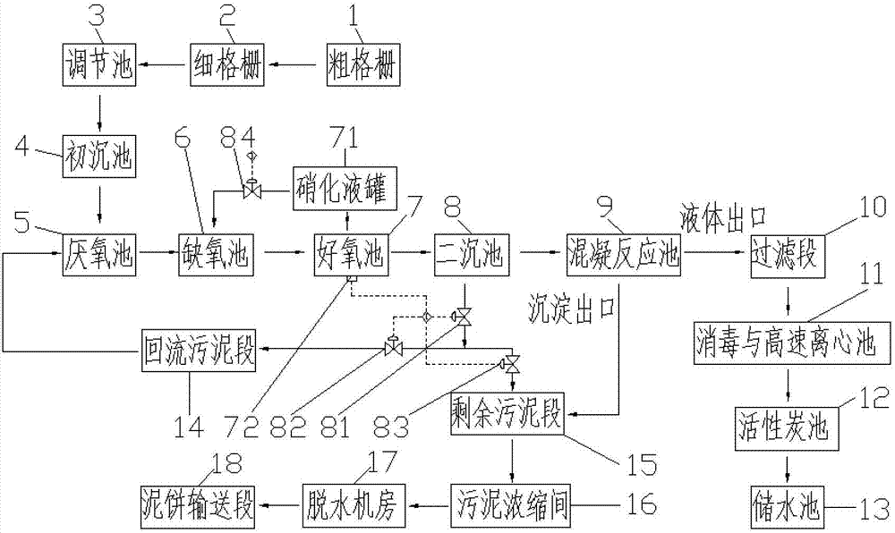
[0033] Such as figure 1 , a sewage treatment system, including a coarse grid 1, a fine grid 2, a regulating tank 3, a primary sedimentation tank 4, an anaerobic tank 5, an anoxic tank 6, an aerobic tank 7, and a secondary sedimentation tank connected by pipelines in sequence pool 8, coagulation reaction pool 9, filter section 10, disinfection and high-speed centrifugal pool 11, activated carbon pool 12, water storage pool 13;

[0034] The coarse grid 1 is divided into a first coarse grid and a second coarse grid, the first coarse grid has a grid pitch of 30-50mm, and the second coarse grid has a grid pitch of 12- 20mm, the pitch of the fine grid 2 is 4-8mm;

[0035]The secondary settling tank 8 is connected downward to the first control valve 81, and a part of the sludge produced by the secondary settling tank 8 is connected to the second control valve 82, and flows back to the anaerobic tank 5 through the return sludge section 14. The other part of the sludge is connected t...

Embodiment 2

[0053] Such as figure 1 , a sewage treatment system, including a coarse grid 1, a fine grid 2, a regulating tank 3, a primary sedimentation tank 4, an anaerobic tank 5, an anoxic tank 6, an aerobic tank 7, and a secondary sedimentation tank connected by pipelines in sequence pool 8, coagulation reaction pool 9, filter section 10, disinfection and high-speed centrifugal pool 11, activated carbon pool 12, water storage pool 13;

[0054] The coarse grid 1 is divided into a first coarse grid and a second coarse grid, the first coarse grid has a grid pitch of 30-50mm, and the second coarse grid has a grid pitch of 12- 20mm, the pitch of the fine grid 2 is 4-8mm;

[0055] The secondary settling tank 8 is connected downward to the first control valve 81, and a part of the sludge produced by the secondary settling tank 8 is connected to the second control valve 82, and flows back to the anaerobic tank 5 through the return sludge section 14. The other part of the sludge is connected ...

Embodiment 3

[0062] Such as figure 1 , a sewage treatment system, including a coarse grid 1, a fine grid 2, a regulating tank 3, a primary sedimentation tank 4, an anaerobic tank 5, an anoxic tank 6, an aerobic tank 7, and a secondary sedimentation tank connected by pipelines in sequence pool 8, coagulation reaction pool 9, filter section 10, disinfection and high-speed centrifugal pool 11, activated carbon pool 12, water storage pool 13;

[0063] The coarse grid 1 is divided into a first coarse grid and a second coarse grid, the first coarse grid has a grid pitch of 30-50mm, and the second coarse grid has a grid pitch of 12- 20mm, the pitch of the fine grid 2 is 4-8mm;

[0064] The secondary settling tank 8 is connected downward to the first control valve 81, and a part of the sludge produced by the secondary settling tank 8 is connected to the second control valve 82, and flows back to the anaerobic tank 5 through the return sludge section 14. The other part of the sludge is connected ...


PUM


Abstract

The invention discloses a sewage treatment system, comprising a coarse grid, a fine grid, an adjustment pond, a primary sedimentation pond, an anaerobic pond, an anoxic pond, an aerobic pond, a secondary sedimentation pond, a coagulation reaction tank, a filtration section, a disinfection and high-speed centrifugal pond, an activated carbon pond and a water storage pond which are sequentially connected by pipes; the secondary sedimentation pond is downwards connected with a first control valve, part of the sludge generated by the secondary sedimentation pond is connected with a second control valve, and returns to the anaerobic pond through a returned sludge section, the other part of the sludge is connected to a third control valve, passes through a surplus sludge section and then is backwards connected with a sludge concentration room, a dehydration room, and a mud cake delivery section; the liquid outlet of the coagulation reaction pond is connected with the disinfection and high-speed centrifugation pond, the sediment outlet is connected with the surplus sludge section, the inlet of the anoxic pond is connected with a nitrification liquid tank, and the aerobic pond is also provided with a detection mechanism. The system and the method of the invention have the advantages of flexible and efficient process and excellent removal effect on various organic pollutants, especially nitrogen, combination of batch processing and continuous processing, and certain-extent automation.

Description

technical field [0001] The invention relates to the field of sewage treatment, in particular to a sewage treatment system and a sewage treatment method. Background technique [0002] With the country's industrial upgrading and structural transformation, the treatment requirements and depth of industrial wastewater are getting higher and higher. In order to ensure the efficient and stable operation of the sewage treatment process, the sewage treatment can put forward higher requirements for the control system, not only to meet the parameter requirements of the "Pollutant Discharge Standards for Urban Sewage Treatment Plants" (GB18918-2002), but also to meet the requirements of intensive production. needs of transformation. [0003] At present, the main treatment processes of domestic sewage in towns and villages are mostly A2O, A / O, oxidation ditch and SBR processes, etc., which are relatively mature. Disadvantages such as high energy consumption, long process flow, complic...

Claims


Application Information

Patent Timeline
IPC IPC(8): C02F9/14
CPCC02F1/001C02F1/283C02F1/32C02F1/38C02F1/5236C02F1/56C02F1/66C02F1/78C02F3/30C02F9/00C02F2001/007C02F2301/08C02F2303/04
Inventor 杨爽侯绍刚田大勇
Owner ANYANG INST OF TECH
Why Eureka
Try Eureka