Icing-resisting road and construction method thereof

An anti-icing and road technology, applied in the direction of roads, roads, coagulation pavement paved on site, etc., can solve the problems of asphalt and cement concrete denudation, great influence of environmental temperature, and inability to remove cleanly, to prevent the road surface. Freezing, simple and easy construction methods, and the effect of improving work timeliness

Active Publication Date: 2017-12-19
UNIV OF JINAN
View PDF4 Cites 8 Cited by
  • Summary
  • Abstract
  • Description
  • Claims
  • Application Information

AI Technical Summary

Problems solved by technology

The mechanical method is to directly act on the road ice accumulation and compacted snow through mechanical devices. It mainly includes impact ice breaking, multi-section whip whipping deicing, roller rotating ice removal and shovel removal, etc., but ice accumulation and compacted snow are combined with the road surface. Tight, if the strength of the deicing machine is too small, the two cannot be separated and cannot be removed cleanly; if the strength is too large, it will damage the road markings, or even destroy the road surface, and the technical level is low, the reliability is poor, there are many failures, and the service life is short
[0004] The chemical method uses chemical agents to reduce the melting point of ice and snow, but it is greatly affected by the ambient temperature. If the temperature is too low, the effect will be significantly reduced, and the chemical agents will cause serious erosion of asphalt and cement concrete, and the damage speed will be much faster than ordinary freeze-thaw cycles. The damage caused by it also causes corrosion pollution to soil, crops and surface water, etc.

Method used


Image

  • Icing-resisting road and construction method thereof
  • Icing-resisting road and construction method thereof

Examples


Embodiment 1

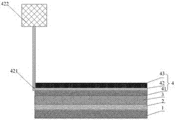
[0033] Such as figure 1 As shown, the anti-icing road provided in Example 1 includes a graded crushed stone layer 1, a cement stabilized base layer 2, a stabilized crushed stone layer 3 and an asphalt concrete layer 4 distributed sequentially from bottom to top, and the asphalt concrete layer It includes an asphalt concrete lower layer 41 , an oil pipe layer 42 and an asphalt concrete upper layer 43 distributed sequentially from bottom to top. The oil pipe layer includes evenly laid and connected oil pipes 421. In this embodiment, the oil pipes 421 are distributed in an S shape, and the laying distance L of the oil pipes 421 is 50 cm. The oil pipe 421 is connected to the solar heat absorbing panel 422 outside the anti-icing road. In practical application, the solar heat absorbing plate 422 can be installed on the street lamp, and the oil pipe 422 is connected to the solar heat absorbing plate 422 installed on the street lamp according to the distribution of the street lamp an...

Embodiment 2

[0045] The structure of the anti-icing asphalt concrete layer that present embodiment 2 provides is identical with embodiment 1, can refer to figure 1, including a graded crushed stone layer 1, a cement stabilized base layer 2, a stabilized crushed stone layer 3 and an asphalt concrete layer 4 distributed sequentially from bottom to top, and the asphalt concrete layer includes an asphalt concrete lower layer 41, oil pipe layer 42 and Asphalt concrete upper layer 43. The oil pipe layer includes evenly laid and connected oil pipes 421 . In this embodiment, the oil pipes 421 are distributed in an S shape, and the laying interval L of the oil pipes 421 is 60 cm. The oil pipe 421 is connected to the solar heat absorbing panel 422 outside the anti-icing road. In practical application, the solar heat absorbing plate 422 can be installed on the street lamp, and the oil pipe 422 is connected to the solar heat absorbing plate 422 installed on the street lamp according to the distributi...

Embodiment 3

[0057] The structure of the anti-icing asphalt concrete layer that present embodiment 3 provides is identical with embodiment 1, can refer to figure 1 , including a graded crushed stone layer 1, a cement stabilized base layer 2, a stabilized crushed stone layer 3 and an asphalt concrete layer 4 distributed sequentially from bottom to top, and the asphalt concrete layer includes an asphalt concrete lower layer 41, oil pipe layer 42 and Asphalt concrete upper layer 43. The oil pipe layer includes evenly laid and connected oil pipes 421 . In this embodiment, the oil pipes 421 are distributed in parallel, and the laying interval L of the oil pipes 421 is 60 cm. The oil pipe 421 is connected to the solar heat absorbing panel 422 outside the anti-icing road. In practical application, the solar heat absorbing plate 422 can be installed on the street lamp, and the oil pipe 422 is connected to the solar heat absorbing plate 422 installed on the street lamp according to the distributio...


PUM

PropertyMeasurementUnit
Phase transition temperatureaaaaaaaaaa
Radiusaaaaaaaaaa
Specific surface areaaaaaaaaaaa

Abstract

The invention provides an icing-resisting road and a construction method thereof. The icing-resisting road comprises a graded rubble layer, a cement stable base layer, a stable rubble layer and a bituminous concrete layer which are sequentially distributed from bottom to top. The bituminous concrete layer comprises a bituminous concrete lower layer, an oil pipe layer and a bituminous concrete upper layer which are sequentially distributed from bottom to top. The oil pipe layer comprises oil pipes which are uniformly laid and communicate, and the oil pipes are connected with a solar heat-absorption plate; the bituminous concrete lower layer and the bituminous concrete upper layer are both obtained through laying of a mixture; the mixture is formed by mixing rubbles, bitumen, a phase transformation unit and steel fibers; the interior of the phase transformation unit is spherical phase transformation paraffin wax, and the exterior of the phase transformation unit is a wrapping layer which is formed by mixing graphene, nanometer aluminum oxide, heat conduction fibers, cement and water; and the phase transformation temperature of the phase transformation paraffin wax is 0-5 DEG C. The icing-resisting road is easy to construct and good in icing-resisting effect.

Description

technical field [0001] The invention belongs to the technical field of road engineering, and in particular relates to an anti-icing road and a construction method thereof. Background technique [0002] In winter and early spring when the temperature is lower than 0°C, the snow may freeze on the road immediately or melt and form road icing on the road due to the drop in temperature. As long as the temperature does not rise enough to thaw the ice, it will remain rock-solid and an important culprit of traffic accidents. The existing road is distributed with graded crushed stone layer, cement stabilized base layer, stabilized crushed stone layer and asphalt concrete layer successively from bottom to top. [0003] At present, road deicing mainly adopts mechanical and chemical methods. The mechanical method is to directly act on the road ice accumulation and compacted snow through mechanical devices. It mainly includes impact ice breaking, multi-section whip whipping deicing, ro...

Claims


Application Information

Patent Timeline
IPC IPC(8): E01C7/32E01C11/26
CPCE01C7/32E01C11/26
Inventor 宫晨琛周竞平芦令超程新
Owner UNIV OF JINAN
Why Eureka
Try Eureka