
Dust control system and method for thermal power plant

A technology for thermal power plants and dust, which is applied in separation methods, chemical instruments and methods, and separation of dispersed particles. It can solve the problems of low dust collection rate, injury to on-site workers, and influence on dust removal effect, etc., and achieves good biodegradability. , wide application range, high haze removal efficiency

Inactive Publication Date: 2017-12-29
XIANGTAN UNIV
View PDF6 Cites 7 Cited by
  • Summary
  • Abstract
  • Description
  • Claims
  • Application Information

AI Technical Summary

Problems solved by technology

There are the following disadvantages: (1) The cloth bag has high water absorption, is easy to scale, is not antistatic, is not flame retardant, and has poor ventilation for long-term work, which affects the dust removal effect; (2) The dust collector produces secondary pollution during the dust removal process; (3) ) Unreasonable and unscientific cleaning of the dust collector will cause energy loss; (4) The equipment is easy to age, the maintenance cost is high, the maintenance workload is large, the service life is short, and the floor area is large; (5) When the pollution source is scattered Dust is difficult to collect, and when some characteristic dust (such as: coal dust) reaches a certain concentration, it will explode under the conditions of high temperature, open flame, electric spark, friction, and impact; (6) the dust gas must be considered when selecting filter materials Generally, the filter material is required to have the characteristics of wear resistance, corrosion resistance, low resistance, and long service life, which increases the manufacturing cost of the filter bag; (7) The nature of the filter material determines that the bag filter has limitations relative to dust (8) The control effect is poor. Although the emission value reaches the 50 mg / m3 allowed by the state, the control indicators of the pollution site are all below the 10 mg / m3 stipulated by the state.
There are the following disadvantages: (1) high primary investment and large steel consumption; (2) electrostatic precipitators usually require high manufacturing and installation precision, otherwise their normal and efficient operation cannot be guaranteed; (3) electrostatic precipitators are low due to the low wind speed However, it occupies a large area; (4) The electrostatic precipitator has certain requirements for the dust to be processed. For the dust outside the suitable range, corresponding measures must be taken to ensure the necessary dust removal performance.
There are the following disadvantages: (1) large investment; (2) low dust collection rate; (3) horizontal pipes are easy to block, which affects the collection rate; (4) purification efficiency is low (usually 40% to 50%); ( 5) Large footprint
There are the following disadvantages: (1) the nozzle is easy to block; (2) the equipment failure rate is high and the maintenance cost is high; (3) for the dust of the moving equipment, the control effect of the dust point can only reach 30% to 40%; (4) Due to the blockage of the nozzle, the pipe joint is easy to burst; (5) The safety factor is low. Since the equipment uses a high-pressure pump to pressurize the water to 6MP-8MP, once the pipe bursts or breaks open, it will cause injury to the on-site staff and the on-site Unnecessary losses caused by equipment; (6) High requirements on the purity of water sources; (7) Filters are easy to block
[0008] Due to the above deficiencies in various dust removal equipment, the dust index of thermal power plants still cannot reach the standard level, and dust control is imminent

Method used


Image

  • Dust control system and method for thermal power plant
  • Dust control system and method for thermal power plant
  • Dust control system and method for thermal power plant

Examples


Embodiment Construction

[0037] The present invention will be further described below in conjunction with the accompanying drawings and specific embodiments.

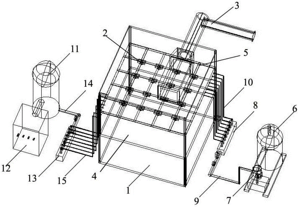
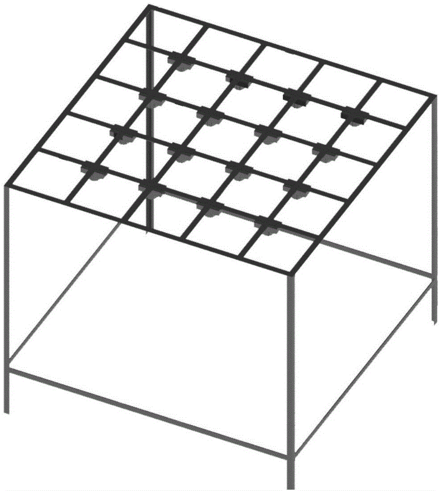
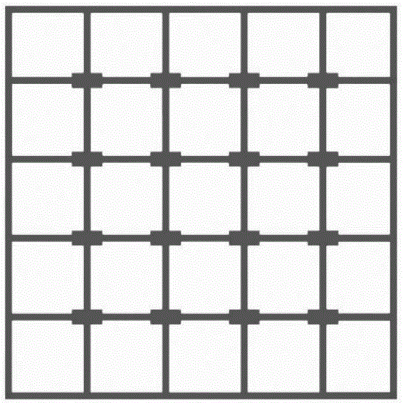
[0038] see Figure 1-Figure 4, a thermal power plant dust control system, including a base 1, a water supply system, a gas supply system, a two-phase flow nozzle 2 and a suction pipe 3, a sealed deposition chamber 4 is formed in the base 1, and a two-phase flow nozzle 2 Arranged on the top of the deposition chamber 4, the water supply system and the gas supply system communicate with the water inlet and the air inlet of the two-phase flow nozzle 2 respectively, and the two opposite side walls of the deposition chamber 4 are respectively provided with an inlet port and an air outlet port, the suction duct 3 is connected to the inlet port of the deposition chamber, and a fan is arranged on the suction duct 3, and the fan sucks the dust-laden gas into the deposition chamber. The present invention changes the atomization performance of the nozzle b...


PUM


Abstract

The invention discloses a dust control system and method for a thermal power plant. The system comprises a base, a water supply system, an air supply system, a two-phase flow nozzles and an air suction pipeline and is characterized in that a settling chamber is formed in the base, the two-phase flow nozzles are arranged at the top of the settling chamber, the water supply system and the air supply system are communicated with the two-phase flow nozzles, the air suction pipeline is in butt joint with the air inlet end of the settling chamber, and a fan is arranged on the air suction pipeline. The dust control system has the advantages that sprayed water mist can reach the micron size by regulating air supply and water supply pressure, water mist quantity is changed by regulating the use number of the nozzles, the wetting property of the water is changed by adding surfactant, the sprayed micron-sized water mist collides with and wraps dust to allow the dust to settle, and a spray dust removing effect is achieved; the dust control system is low in cost, low in energy consumption, evident in air purification effect and especially suitable for the purification of the air of an environment with respirable dust.

Description

technical field [0001] The invention relates to the field of dust environment treatment in thermal power plants, in particular to a dust control system and method for thermal power plants. Background technique [0002] In recent years, with the rapid development of my country's social economy, the problem of environmental pollution has become more serious. Not only the frequency of smog weather has become higher and higher, but the severity has also increased compared to before. The emissions from the thermal power industry Dust occupies a considerable proportion. [0003] Silica dust, a kind of occupational hazardous particulate matter with the highest hazard and the widest range of hazards in the power industry, generally refers to the dust of free silica represented by quartz. Silica dust in thermal power plants is generally dust containing less than 10% free silica (the maximum allowable emission mass concentration specified by the state is 10 mg / m3), and 73% of which ha...

Claims


Application Information

Patent Timeline
IPC IPC(8): B01D47/06
CPCB01D47/06B01D2247/08B01D2247/14
Inventor 赵镍丁秋杰齐福刚欧阳晓平李珺煜祝文军张志强王冰陈静
Owner XIANGTAN UNIV
Learn More