Manufacturing method of metal-ceramic composite substrate and composite substrate manufactured through manufacturing method

A technology of ceramic composite and manufacturing method, applied in the field of ceramic metallization, can solve the problems of decreased overcurrent capability of metal-ceramic composite substrate, increased manufacturing cost, increased electrical impedance, etc., and achieves tight bonding, decreased manufacturing cost, and reduced The effect of silver content

Active Publication Date: 2018-01-05
ZHEJIANG TC CERAMIC ELECTRONICS
View PDF8 Cites 10 Cited by
  • Summary
  • Abstract
  • Description
  • Claims
  • Application Information

AI Technical Summary

Problems solved by technology

[0003] However, at present, when the metal-ceramic composite substrate is formed by the AMB process, there is only one layer of brazing material. In order to ensure sufficient eutectic reaction with copper foil at the sintering temperature, this layer of brazing material can obtain a tightly bonded metal-ceramic composite lining. At the bottom, silver content ≥ 72wt% is required, too much silver content will increase the cost
On the other hand, this layer of brazing material needs to contain enough active metal components to react at the entire ceramic-brazing material interface, so the active metal content in the entire brazing material is too much, resulting in an increase in electrical impedance, making the metal-ceramic The flow capacity of the composite substrate is reduced
Such as patent literature [1] and patent literature [2], in order to obtain metal-ceramic composite substrates with non-contact parts, the silver content in the solder is required to be ≥ 90.0%, which greatly increases the manufacturing cost
[0004] Patent document [3] proposes a brazing material using a low content of silver (15% to 35%), but the electrical impedance increases due to the high content of active metal (4 to 8% Ti), and although the adhesion Increased strength, however, the metal plate is prone to cracking when bonded to the ceramic substrate

Method used


Image

  • Manufacturing method of metal-ceramic composite substrate and composite substrate manufactured through manufacturing method
  • Manufacturing method of metal-ceramic composite substrate and composite substrate manufactured through manufacturing method
  • Manufacturing method of metal-ceramic composite substrate and composite substrate manufactured through manufacturing method

Examples


Embodiment 1

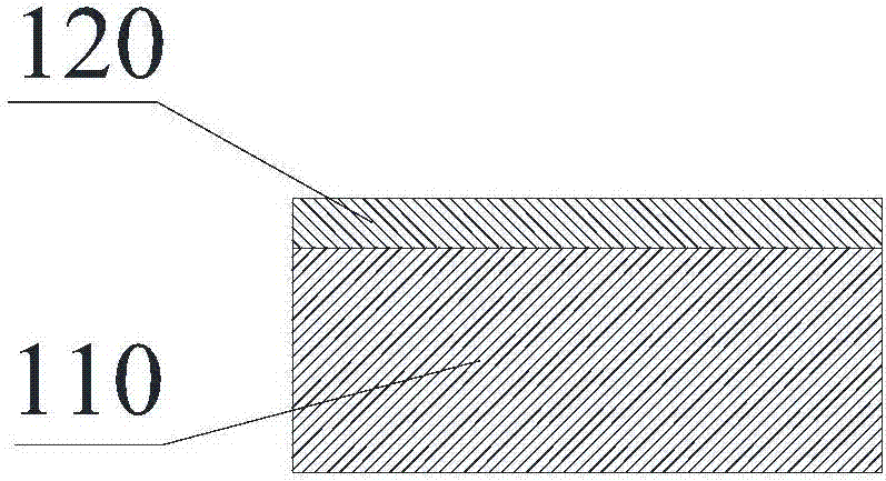
[0047] see figure 1 , printing the first brazing material (6% active metal content, 20% silver content) on the surface of the aluminum nitride ceramic substrate 110 , and drying at 100° C. for 10 minutes to obtain the first brazing material layer 120 .

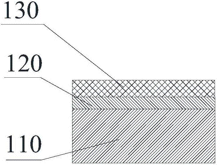
[0048] see figure 2 , printing the second brazing material (active metal content 0%, silver content 72%) on the surface of the first brazing material layer 120 away from the ceramic substrate 110, and drying at 100° C. for 10 minutes to obtain the second brazing material Material layer 130.

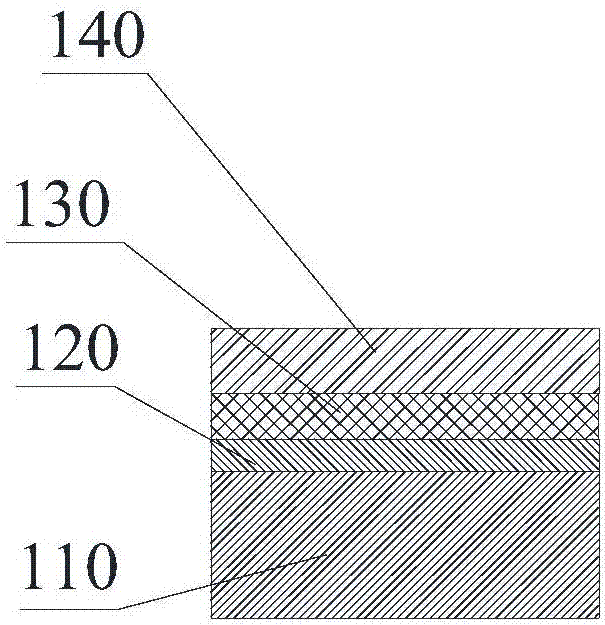
[0049] see image 3 , soak the copper foil at 60°C with 5wt% sodium hydroxide solution for 10 minutes, and wash it twice with distilled water; Second, blow dry. The treated copper foil is placed on the surface of the second solder layer 130 away from the first solder layer 120 to form a copper layer 140 .

[0050] see Figure 4 , the metal-ceramic composite substrate precursor is placed in a vacuum sintering furnace for vacuum sint...

Embodiment 2

[0063] Except that the silver content in the second layer of brazing material was increased to 78%, the rest were prepared in the same manner as in Example 1 to produce a metal-ceramic composite substrate, and the same analysis was carried out. The results are shown in Table 1.

Embodiment 3

[0079] The first copper paste with a viscosity of 300 mPa·s was coated on the surface of the ceramic substrate 110 and dried at 110° C. for 10 minutes to obtain the first solder layer 120 .

[0080] The second copper paste with a viscosity of 50 mPa·s was coated on the surface of the first solder layer 120 away from the ceramic substrate 110 , and dried at 90° C. for 15 minutes to obtain the second solder layer 130 .

[0081] Soak the copper strip in 5wt% sodium hydroxide solution for 5 minutes at 60°C, wash it twice with distilled water; then soak it in 10wt% sulfuric acid solution at room temperature for 1min, and wash it with distilled water twice. The treated copper strip is placed on the surface of the second solder layer 130 away from the first solder layer 120 to form the copper layer 140 .

[0082] The metal-ceramic composite substrate precursor was vacuum sintered in a vacuum sintering furnace at 800° C. for 40 min to obtain a metal-ceramic composite substrate.


PUM

PropertyMeasurementUnit
viscosityaaaaaaaaaa
viscosityaaaaaaaaaa
peel strengthaaaaaaaaaa

Abstract

The invention discloses a manufacturing method of a metal-ceramic composite substrate and the composite substrate manufactured through the manufacturing method and belongs to the technical field of ceramic metallization. The manufacturing method comprises the following steps of forming a first brazing material layer on the surface of a ceramic substrate, wherein the first brazing material layer isa copper, silver and active metal brazing material layer; forming a second brazing material layer on the surface of the first brazing material layer, wherein the second brazing material layer is a copper and silver brazing material layer; forming a copper layer on the surface of the second brazing material layer; and sintering a metal-ceramic composite substrate precursor in vacuum. According tothe manufacturing method, an active metal in the first brazing material layer reacts with ceramic during vacuum sintering, so that the binding force is high and the thermal shock resistance is high. Copper and silver in the second brazing material layer are subjected to eutectic reaction with copper foil, so that the copper and the silver are tightly combined with the copper foil; and meanwhile, by adopting two brazing material layers, on one hand, the content of the silver is reduced and the cost is lower, and on the other hand, the content of the active metal is reduced, electrical impedanceis reduced and the metal-ceramic composite substrate is higher in high voltage resistance and high current resistance.

Description

technical field [0001] The invention relates to the technical field of ceramic metallization, in particular to a method for manufacturing a metal-ceramic composite substrate and the manufactured composite substrate. Background technique [0002] There are two general methods for manufacturing ceramic circuit boards of power modules or installing semiconductors on them. One is direct copper clad technology (DBC), which uses metal oxides as transition layers on ceramic substrates in an open or semi-open environment. Copper foil is directly covered on the top, so that the two are bonded to each other. The other is active metal brazing technology (AMB), which uses brazing materials containing active metals such as Ti, Zr or Hf to heat and weld the copper foil and the ceramic substrate together in a vacuum protection environment, so that the ceramic substrate and copper The foils are bonded to each other. Among them, the metal-ceramic composite substrate made by the AMB process...

Claims


Application Information

Patent Timeline
Patent Type & Authority Applications(China)
IPC IPC(8): H01L21/48H01L23/15H01L23/492
CPCH01L21/4821H01L23/49866
Inventor 钱建波孙林袁超于岩王顾峰聂朝轩王太保黄世东胡士刚
Owner ZHEJIANG TC CERAMIC ELECTRONICS
Why Eureka
Try Eureka