Preparation and Application of Membrane Electrode Based on Platinum or Platinum Alloy Nanotubes
A technology of membrane electrodes and platinum alloys, applied in battery electrodes, circuits, fuel cells, etc., can solve the problems of high consumption of precious metals, disorderly accumulation of catalysts, and low utilization of catalysts, and achieve thin catalytic layer thickness and low catalyst composition. Adjustable, mild preparation conditions
- Summary
- Abstract
- Description
- Claims
- Application Information
AI Technical Summary
Problems solved by technology
Method used
Image
Examples
Embodiment 1
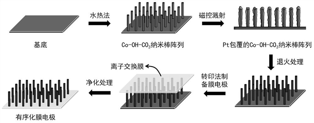
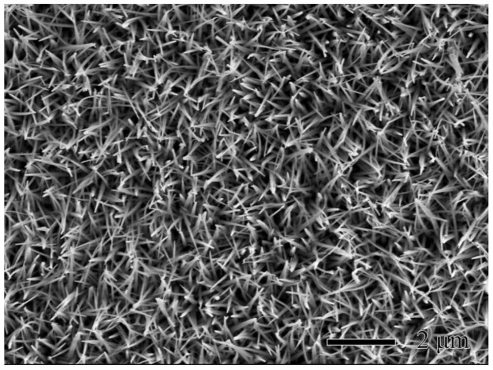
[0040] Preparation of Co-OH-CO by hydrothermal method using stainless steel as substrate 3 array. The reaction solution was 10 mM ammonium fluoride, 25 mM urea, and 5 mM cobalt nitrate. React in a high-pressure reactor at 120°C for 5 hours to prepare Co-OH-CO on the substrate 3 array. figure 2 Shown is the prepared Co-OH-CO 3 SEM image of the nanorod array. It can be seen from the figure that Co-OH-CO 3 The nanorod array grows uniformly on the substrate, and the growth direction is substantially perpendicular to the substrate. Co-OH-CO 3 The length of the nanorod is about 3μm, the diameter is about 100nm, Co-OH-CO 3 The areal density of nanorods is 3-4e 9 / cm 2 .
[0041] Co-OH-CO was deposited by magnetron sputtering 3Pt is loaded on the array. The magnetron sputtering power is 150W, the sputtering time is 10min, and the operating pressure is 1.0Pa. Co-OH-CO loaded with Pt 3 array at 300°C, H 2 -Ar(H 2 The volume fraction is 5%) and annealed for 60 min in an ...
Embodiment 2
[0047] Preparation of Co-OH-CO by hydrothermal method using stainless steel as substrate 3 array. The reaction solution was 10 mM ammonium fluoride, 25 mM urea, and 5 mM cobalt nitrate. React in a high-pressure reactor at 120°C for 4 hours to prepare Co-OH-CO on the substrate 3 array.
[0048] Co-OH-CO was deposited by magnetron sputtering 3 PtCo (atomic ratio 3:1) is supported on the array. The magnetron sputtering power is 100W, the sputtering time is 20min, and the operating pressure is 1.0Pa. Co-OH-CO loaded with PtCo 3 array at 400°C, H 2 -Ar(H 2 The volume fraction is 5%) and annealed for 1 h under the atmosphere. Figure 7 Shown is the SEM image of the as-prepared platinum-cobalt nanotube array. It can be seen from the figure that magnetron sputtering in Co-OH-CO 3 The uniform PtCo catalyst is loaded on the surface of the nanorod array, the thickness of the PtCo coating is about 18nm, and the annealing treatment does not destroy the order of the array. Co-OH-...
Embodiment 3
[0053] Co-OH-CO 3 Refer to Example 2 for the preparation method of the array.
[0054] Co-OH-CO was deposited by magnetron sputtering 3 PtFe (atomic ratio 1:1) is supported on the array. The magnetron sputtering power is 100W, the sputtering time is 20min, and the operating pressure is 1.0Pa. Co-OH-CO loaded with PtFe 3 array at 600°C, H 2 -Ar(H 2 The volume fraction is 5%) and annealed for 1 h under the atmosphere. Figure 11 Shown is the scanning electron microscope image of the prepared nanorod array. It can be seen from the figure that the prepared PtFe nanorods grow vertically on the substrate with a certain orientation, and the Co-OH-CO loaded with PtFe coating 3 The nanorods are about 2.5 μm in length and about 130 nm in diameter.
[0055] Refer to Example 2 for the preparation process of the membrane electrode. Figure 12 It is a scanning electron microscope picture of the prepared membrane electrode. It can be seen from the picture that the prepared catalytic ...
PUM
| Property | Measurement | Unit |
|---|---|---|
| diameter | aaaaa | aaaaa |
| length | aaaaa | aaaaa |
| thickness | aaaaa | aaaaa |
Abstract
Description
Claims
Application Information
 - R&D
- Intellectual Property
- Life Sciences
- Materials
- Tech Scout
- Unparalleled Data Quality
- Higher Quality Content
- 60% Fewer Hallucinations
Browse by: Latest US Patents, China's latest patents, Technical Efficacy Thesaurus, Application Domain, Technology Topic, Popular Technical Reports.
© 2025 PatSnap. All rights reserved.Legal|Privacy policy|Modern Slavery Act Transparency Statement|Sitemap|About US| Contact US: help@patsnap.com


