Optical antenna of free space optical communication system, and automatic alignment method thereof

An optical communication system and optical antenna technology, applied in the field of optical communication, can solve problems such as poor environmental adaptability, inability to achieve long-distance transmission, and laser beam wavefront distortion.

Pending Publication Date: 2018-01-26
LANZHOU UNIVERSITY OF TECHNOLOGY
View PDF0 Cites 3 Cited by
  • Summary
  • Abstract
  • Description
  • Claims
  • Application Information

AI Technical Summary

Problems solved by technology

However, there are still the following problems in the application of this optical antenna system: 1. When applied in the atmosphere, the attenuation of the atmosphere is relatively serious, and the randomness of the atmospheric channel is strong, making it difficult to accurately align, capture, and maintain, and the effect of atmospheric turbulence It is easy to cause the wavefront distortion of the transmitted laser beam, so that the light intensity changes and the signal part is lost; 2. When the transceiver is installed on the building, the vibration of the building and the disturbance of the wind will make it difficult to align, and even the signal will be lost. Interruption; 3. The transmission efficiency of the currently used optical antenna is low
However, this technology still cannot achieve high-precision alignment, and its adaptability to the environment is not strong, so it cannot achieve the purpose of long-distance transmission, nor can it solve the problem of low transmission efficiency caused by atmospheric disturbances

Method used


Image

  • Optical antenna of free space optical communication system, and automatic alignment method thereof
  • Optical antenna of free space optical communication system, and automatic alignment method thereof
  • Optical antenna of free space optical communication system, and automatic alignment method thereof

Examples


Embodiment Construction

[0058] The present invention will be further described below in conjunction with the accompanying drawings and specific embodiments.

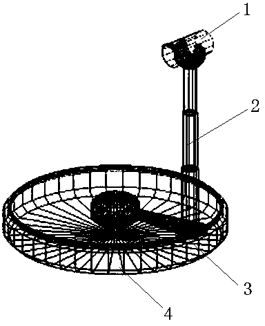
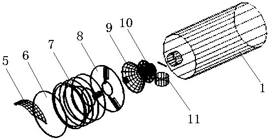
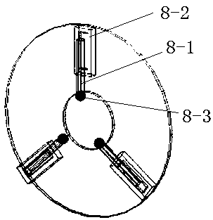
[0059] Such as Figure 1-5 , an optical antenna for a free-space optical communication system, comprising an antenna transmission head housing 1, the front end of the antenna transmission head housing 1 is provided with a dust-proof glass 6, the top of the front end is provided with a shading eaves 5, and the antenna transmission head housing 1 can rotate 360° Set on the top of a telescopic rod 2, the telescopic rod 2 is linked to the surface of the base 4 through a rotating shaft 3 that can rotate along the surface of the base 4; inside the antenna transmission head housing 1, the side away from the top of the telescopic rod 2 is sequentially provided with a stray light elimination diaphragm 7 , collimator 8, Cassegrain antenna 9, pre-collimation device 10 and laser emission receiving device 11; Wherein, the stray light stop 7 is made of sever...


PUM


Abstract

The invention discloses an optical antenna of a free space optical communication system, and an automatic alignment method thereof, and belongs to the field of optical communication technology. The optical antenna comprises an antenna transmission head shell arranged at the top of a telescopic rod in a manner of being rotated for 360 degrees, and the telescopic rod is connected to the surface of the base via a rotating shaft that can rotate around the surface of the base, wherein a stray light aperture, a collimator, a Cassegrain antenna with an open secondary mirror, a pre-collimating deviceand a laser transmitting and receiving device are arranged on one side in the antenna transmission head shell away from the telescopic rod in sequence; the laser transmitting and receiving device comprises a semiconductor laser emission laser and a receiver; and the collimator comprises three detectors in central symmetry, and laser intensity sensors are arranged in the detectors. The laser beamsof the optical antenna are primarily aligned by using coordinate transformation of space to right angle, with the three vertexes of an equilateral triangle formed in the detector as foundation, accurate alignment is achieved by one-by-one alignment method, and the optical antenna can be applied to waveforms subjected to any deformation and information loss.

Description

technical field [0001] The invention belongs to the technical field of optical communication, in particular to an optical antenna of a free-space optical communication system and a method for automatically aligning the antenna. Background technique [0002] With the continuous development of communication technology, people hope that the transmission rate will be higher and higher. The communication technologies currently used are mainly microwave communication technology and optical fiber communication technology. However, the microwave communication technology uses a long wavelength, which makes the equipment bulky, and the weight and power consumption are relatively large, and the transmission rate and communication capacity cannot meet the requirements. Optical fiber communication is the first choice for access in the current development, but when there is a lack of optical cable resources, it is not convenient to lay optical cables, or it is too late to lay optical cab...

Claims


Application Information

Patent Timeline
Patent Type & Authority Applications(China)
IPC IPC(8): H04B10/11
CPCY02D30/70
Inventor 王首鹏徐雨萌赵奇飞孔鸿鹏王道斌
Owner LANZHOU UNIVERSITY OF TECHNOLOGY
Why Eureka
Try Eureka