PDC drill bit capable of achieving fast drilling in soft and hard interbedded rock

A rock-fast technology, applied in the field of PDC bits, which can solve the problems of short bit life, unsatisfactory cooling effect, chipping and tooth chipping

Pending Publication Date: 2018-01-30
SINOHYDRO BEREAU 10 CO LTD
View PDF8 Cites 1 Cited by
  • Summary
  • Abstract
  • Description
  • Claims
  • Application Information

AI Technical Summary

Problems solved by technology

[0004] However, the traditional PDC bit also has the following defects: firstly, due to the small contact area of ​​the PDC bit at the bottom of the hole, the specific pressure is high, and the PDC is wear-resistant, self-sharpening, and the cutting edge is sharp, so the aging effect is high, and cuttings (or However, in some viscous formations, due to the strong adhesion of the cuttings, traditional PDC bits tend to be easily blocked and stick to the front of the cutting teeth to form mud Packed or paste drill, the drilling rate is slow; secondly, the erosion resistance of the traditional PDC drill bit and the wear resistance of the steel body of the drill bit are relatively poor, and the life of the drill bit is relatively short; thirdly, PDC is a composite superhard material, and its performance is It is hard and wear-resistant, but its temperature resistance is very poor, so the temperature cannot exceed 650°C during use, so it puts forward high requirements for the timely and sufficient cooling of the drill bit, but the cooling effect of the traditional PDC drill bit is not satisfactory; the final PDC comparison Hard and brittle, you should avoid impact, otherwise it will come off and chip. However, traditional PDC drills are subject to greater impact, and sometimes chip off and chip.

Method used


Image

  • PDC drill bit capable of achieving fast drilling in soft and hard interbedded rock
  • PDC drill bit capable of achieving fast drilling in soft and hard interbedded rock
  • PDC drill bit capable of achieving fast drilling in soft and hard interbedded rock

Examples


Embodiment Construction

[0019] The present invention will be further described below in conjunction with accompanying drawing:

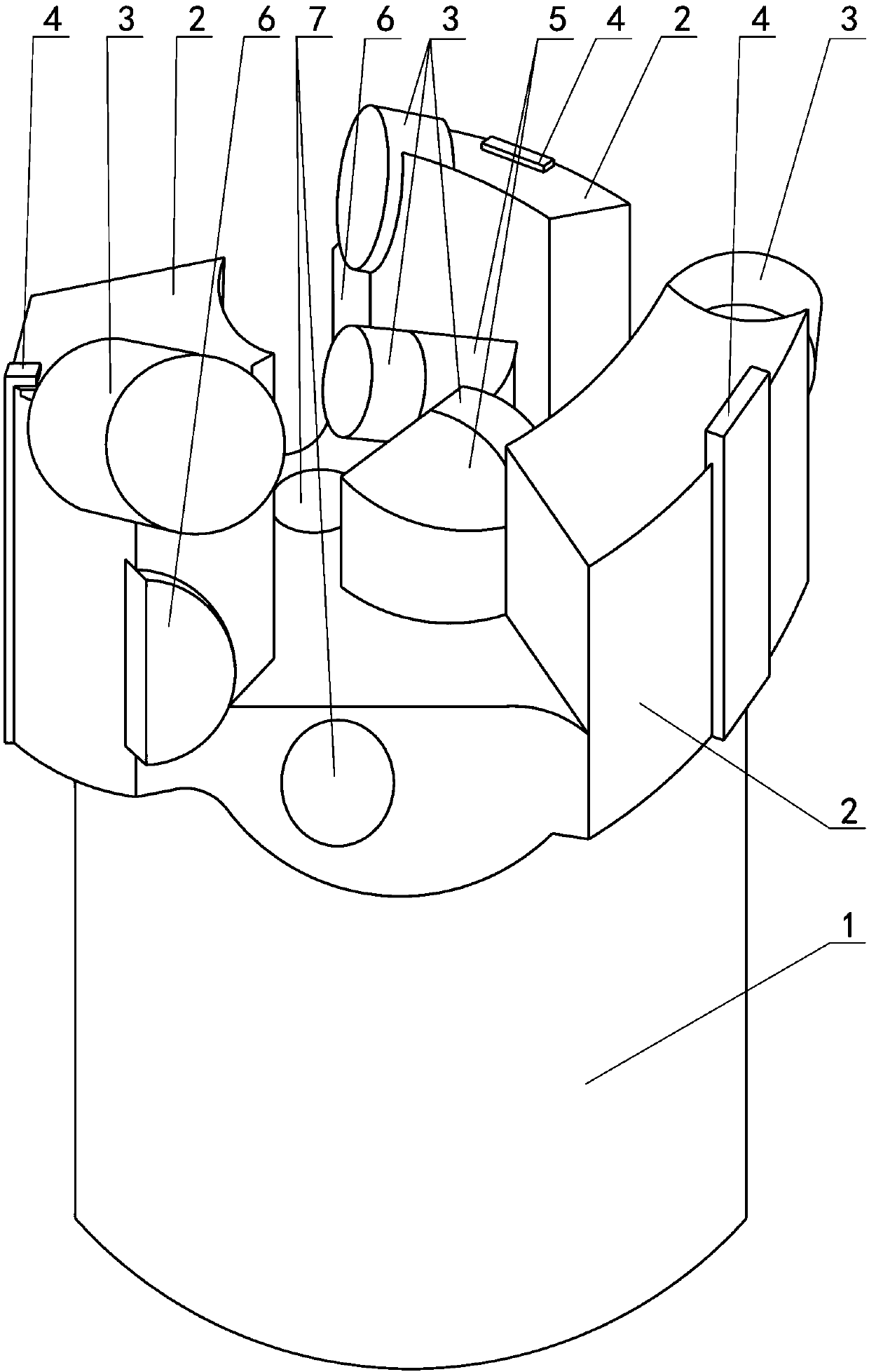
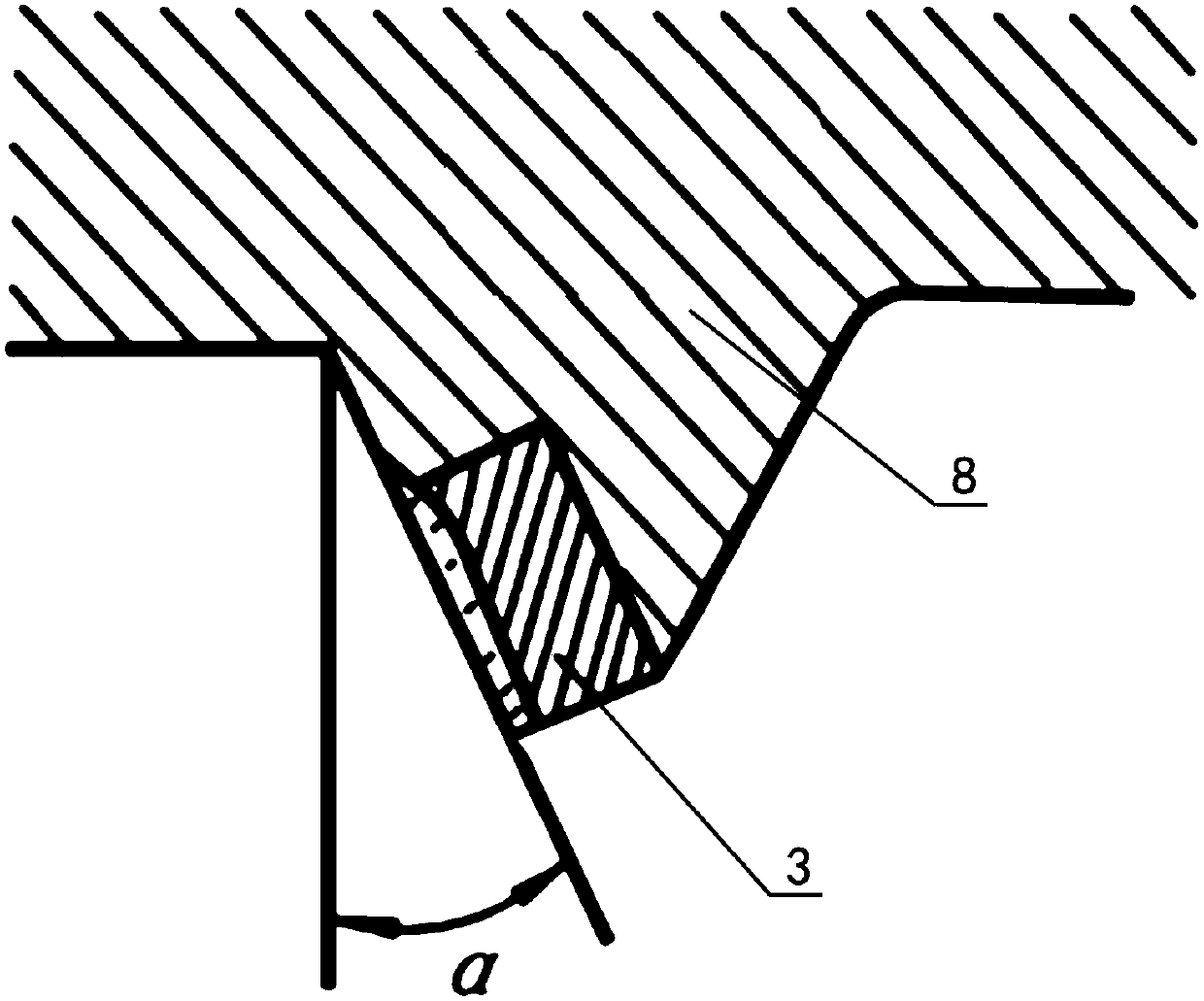
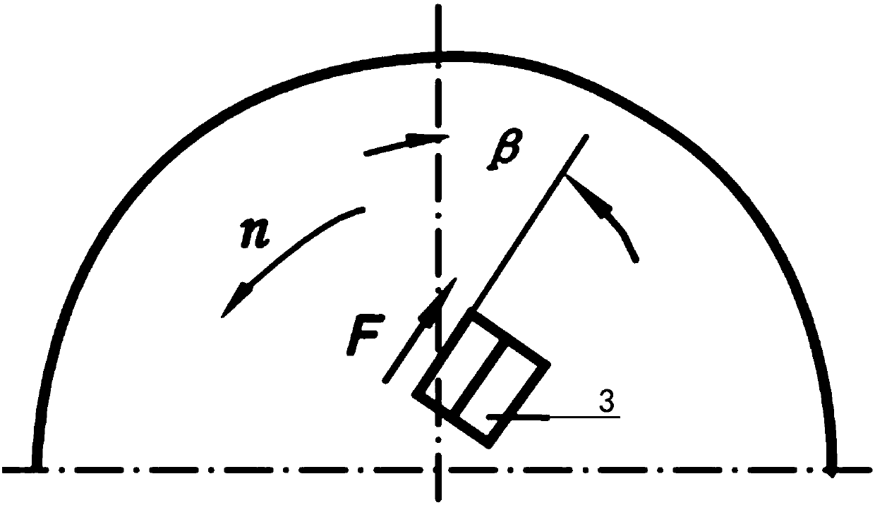
[0020] Such as Figure 1-Figure 5 As shown, the PDC drill bit described in the present invention that can drill rapidly in soft and hard interbedded rocks includes a drill bit body 8 ( figure 1 Not marked in, see Figure 2-Figure 5 The drill bit body 8) and the joint rigid body 1, the drill bit body 8 is located at the upper end of the joint rigid body 1 (see figure 1 In the upper end, here is only the direction defined for the convenience of expression, it is the front end during actual application), the lower end of the joint rigid body 1 is used to connect the drill pipe (not shown in the figure), and the outer periphery of the drill bit body 8 is evenly provided with three outer Blade 2, the middle part of the drill body 8 is provided with two center blades 5, the top of the center blade 5 is lower than the top of the outer blade 2, one side upper part of each outer b...


PUM


Abstract

The invention discloses a PDC drill bit capable of achieving fast drilling in soft and hard interbedded rock. The PDC drill bit comprises a drill bit body and a connector rigid body and is characterized in that three outer blades are evenly arranged on the outer periphery of the drill bit body, two central blades are arranged in the middle of the drill bit body, a cylindrical PDC is arranged on the upper portion of one side of each outer blade, a cylindrical PDC is arranged on the upper portion of one side of each central blade, the negative rake of each cylindrical PDC is 13-18 degrees, the bypass angle of each cylindrical PDC is 3-5 degrees, and the exposure height of each cylindrical PDC is 10.9-11.2mm. The PDC drill bit has the advantages that by designing the three high outer blades and the two low central blades, mounting the cylindrical PDC on each blade and optimally designing the negative rake, the bypass angle and the exposure height of each cylindrical PDC, the tooth breakage problem of the drill bit during cutting can be prevented, rock powder after cutting can be fast discharged out of the drill bit body, optimal drilling rate and optimal chip removing rate are achieved, the overall drilling speed of the PDC drill bit is increased evidently, and the service life of the drill bit is prolonged.

Description

technical field [0001] The invention relates to a PDC drill bit, in particular to a PDC drill bit capable of rapidly drilling in soft and hard interbedded rocks. Background technique [0002] PDC bit is the abbreviation of polycrystalline diamond compact bit. It is a drilling tool commonly used in the geological drilling industry. It is evolved from diamond drill. It is called PDC bit because of the PDC on the bit body. The English corresponding to PDC is: Polycrystalline Diamond Compactbit, that is, polycrystalline diamond composite sheet. [0003] PDC drills are cutting drills. According to the mechanical properties of the rock, the tensile strength of the cutting drill bit is required to be the lowest, followed by the shear strength, while the compressive strength is the highest, and the compressive strength is often several times or even more than ten times higher than the shear strength. Therefore, utilizing the tool of shearing or cutting mode to break rock must be a...

Claims


Application Information

Patent Timeline
Patent Type & Authority Applications(China)
IPC IPC(8): E21B10/43E21B10/54E21B10/56E21B10/60
Inventor 刘寒剑王荣钟林刘炜范正春邓树密赵启强
Owner SINOHYDRO BEREAU 10 CO LTD
Why Eureka
Try Eureka