
New method and system for TSV blind hole filling

A new method, the technology of blind vias, is applied in electrolytic coatings, circuits, semiconductor devices, etc., and can solve problems such as high production costs, high aspect ratio TSV plating filling efficiency, low current density, etc.

Inactive Publication Date: 2018-02-09
CENT SOUTH UNIV
View PDF4 Cites 8 Cited by
  • Summary
  • Abstract
  • Description
  • Claims
  • Application Information

AI Technical Summary

Problems solved by technology

[0005] In the above process, the principle of electroplating deposition in a mixed acidic solution is adopted. In order to avoid voids and gaps, it is necessary to use a small current density and consume a long time, resulting in low filling efficiency of high aspect ratio TSV plating. High production costs

Method used


Image

  • New method and system for TSV blind hole filling

Examples


Embodiment Construction

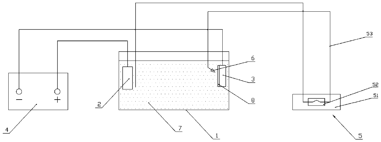
[0026] Such as figure 1 As shown, the TSV blind hole filling system provided in this embodiment includes an electroplating tank 1, an electroplating anode 2, an electroplating cathode 3, an electroplating power supply 4, a peristaltic pump 5, a nozzle 6 and an electroplating solution 7 added to the electroplating tank . Wherein the peristaltic pump 5 includes a driver 51, a pump head 52 and a flexible pipe 53, the nozzle 6 is connected to the outlet of the flexible pipe, and the electroplating solution 7 is a mixed suspension electroplating solution of copper sulfate electroplating solution, nanoparticles, inhibitors and accelerators, electroplating The anode and the electroplating cathode respectively extend into the electroplating solution and are located on both sides of the electroplating tank.

[0027] This embodiment also provides a new method for filling TSV blind holes, which includes the following steps: Step 1. Put the silicon wafer 8 with TSV blind holes into deion...


PUM


Abstract

The invention discloses a new method and system for TSV blind hole filling. The new method includes the following steps that firstly, a silicon piece with a TSV blind hole is put into deionized water,vacuum suction pretreatment is conducted, and gas in the TSV blind hole is exhausted; secondly, the silicon piece obtained after pretreatment is integrally connected with an electroplating cathode; thirdly, an additive agent, an inhibiting agent and an accelerating agent are added into an electroplating solution, sufficient mixing is conducted, and a suspension electroplating solution is formed;fourthly, the suspension electroplating solution is added into an electroplating bath, an electroplating anode and an electroplating cathode of an electroplating power source are put into the suspension electroplating solution so that the silicon piece can be subjected to standing in the suspension electroplating solution, and the electroplating solution reaches adsorption balance preliminarily inthe TSV blind hole; fifthly, an inlet and an outlet of a circulation pump communicate with the suspension electroplating solution, the inlet communicates with the position of the electroplating anode, and the outlet communicates with the position of the electroplating cathode; and sixthly, a circulation pump is started, the electroplating power source is started at the same time, electroplating begins, and the flowing speed is provided for the suspension electroplating solution in the electroplating bath through the circulation pump. The filling efficiency can be effectively improved, and thecost is reduced.

Description

technical field [0001] The invention belongs to the field of semiconductor three-dimensional packaging, and in particular relates to a new method and system for filling TSV blind holes. Background technique [0002] Three-dimensional integrated manufacturing technology will promote a new round of devices with multiple functions, miniaturization, and high cost performance. In the next 10 years, it will achieve explosive growth in logic devices, sensors, high-bandwidth applications, digital storage, and flash memory, driving the widespread use of high-end chips. application. [0003] At present, a generally accepted method to achieve three-dimensional integration is to use three-dimensional vertical interconnection (Through-Silicon-Via, TSV) through the substrate to realize electrical signal transmission. This technical method can effectively reduce the interconnection length, reduce transmission delay and power consumption, increase data transmission bandwidth, simplify wiri...

Claims


Application Information

Patent Timeline
IPC IPC(8): C25D15/00C25D7/12
CPCC25D15/00C25D7/12
Inventor 王福亮赵志鹏王峰乐玉平
Owner CENT SOUTH UNIV
Learn More