
Thin oil lubrication heating system of cross-cutting production line

A thin oil lubrication and heating system technology, applied in the direction of lubricating parts, engine lubrication, engine components, etc., can solve problems such as affecting heating effect, aggravating oil, oil temperature unevenness, etc., to reduce equipment investment costs, improve Heating capacity and space saving effect

Inactive Publication Date: 2018-02-23
SHAANXI EYOUNG TECH
View PDF0 Cites 1 Cited by
  • Summary
  • Abstract
  • Description
  • Claims
  • Application Information

AI Technical Summary

Problems solved by technology

In order to avoid overheating of the oil, the electric heater adopts the indirect heating method, that is, the electric heater has a finned bushing outside, and the bushing is filled with transformer oil, and the heated transformer oil realizes the heating of the oil tank. The function of the centralized lubrication system is to provide oil-sprayed lubrication to the gear boxes of the disc shears and edge cutters. When the room temperature of the plant is lower than 10°C, when the thin oil centralized lubrication system of the 300,000-ton cross-cutting production line is running, the heater will The following problems were exposed: 1. The sleeve-type electric heaters installed at the bottom of the fuel tank are densely arranged, the layout interval is small, and the fluidity of the oil at the heater is poor, which affects the heating effect; 2. The sleeve-type electric heaters Insufficient heating power of the electric heater causes the heater to be in the heating state for a long time, which seriously shortens the service life of the electric heater; 3. The oil temperature of the system is uneven, and the temperature of the oil tank reaches 40°C, while the oil supply temperature is only 30°C, which is different from the design temperature The difference is large. In addition, the local temperature around the heater sleeve is even as high as 70~80°C, which will aggravate the aging and deterioration of the oil.

Method used


Image

  • Thin oil lubrication heating system of cross-cutting production line

Examples


Embodiment 1

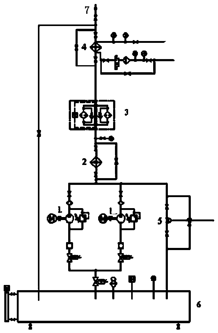
[0014] A thin oil lubrication heating system for a cross-cutting production line according to the present invention includes an oil pipeline 7, the output end of the oil pipeline 7 is connected to the oil tank 6 through a double cylinder filter 3 and a pipeline heater 2, and the oil pipeline 7 A plate cooler 4 is provided between the output end of the liquid pipeline 7 and the duplex filter 3 ; a pneumatic pressure regulating valve 5 is provided between the pipeline heater 2 and the oil tank 6 .

[0015] Both valves are respectively connected with the pneumatic pressure regulating valve 5 .

[0016] The filtration accuracy of the duplex filter 3 in this embodiment is 80 μ.

[0017] The volume of the mailbox described in this embodiment is 5 cubic meters.

[0018] The oil flows out from the oil pipeline 7, passes through the pipeline heater 2, and realizes the heating effect by exchanging heat with the pipeline heater 2, and then enters the oil tank 6 after being filtered by t...

Embodiment 2

[0020] This embodiment is basically the same as Embodiment 1, the difference is that this embodiment is provided with two oil passages between the pipeline heater 2 and the oil tank 6, and each oil passage is provided with a valve, each of which Each oil channel is provided with a screw pump 1, and each screw pump 1 is connected with a motor, and the flow rate of the screw pump 1 is 206 liters per minute. In this embodiment, two screw pumps 1 divide the flow of the liquid in the pipeline heater 2 and then flow into the oil tank 6, which avoids a large loss of oil temperature and relieves the pipeline pressure.


PUM


Abstract

The invention relates to a thin oil lubrication heating system for a cross-cutting production line. It includes an oil pipeline, the output end of the oil pipeline is connected to the oil tank through a double cylinder filter and a pipeline heater, and a plate cooler is arranged between the output end of the oil pipeline and the double cylinder filter; the pipeline There is a pneumatic pressure regulating valve between the type heater and the oil tank. In the system described in the present invention, the heater is installed at the outlet of the oil supply pump, which improves the fluidity of the oil at the heater and improves the heating capacity of the heater system compared with the sleeve electric heater; The circulation loop, on the premise of meeting the heating capacity requirements of the system, reduces equipment investment costs and saves site space, and has a better application effect.

Description

technical field [0001] The invention relates to a thin oil lubrication heating system for a cross-cutting production line. Background technique [0002] Thin oil lubrication system is mainly composed of oil tank, heater, screw pump device, sewage gear pump, filter, pressure controller, cooler, temperature controller, pneumatic valve frame and pressure tank. The thin oil lubrication system is arranged with two oil tanks, one for use and one for standby. The lubricating oil is sucked out from the oil tank by the screw pump, delivered to the lubrication point of the equipment through the duplex filter and the cooler, after lubricating and cooling the equipment, it flows back to the oil tank through the oil return connection to complete a cycle. The pressure tank plays a role in stabilizing the voltage and providing instantaneous protection to the key equipment running at high speed in case of sudden accidents such as power failure. The system adopts the way of oil tank heatin...

Claims


Application Information

Patent Timeline
IPC IPC(8): F16N39/04F16N39/06
CPCF16N39/04F16N39/06F16N2039/007
Inventor 张俊
Owner SHAANXI EYOUNG TECH
Learn More