A full bridge circuit and fast recovery diode

A full-bridge circuit and bridge-connecting technology, applied in circuits, electrical components, electrical solid devices, etc., can solve the problems of complex manufacturing process, heat accumulation at connections, short-circuit operation, etc., to save space requirements and costs, reduce difficulty and complexity, reducing the undesirable effects of open and short circuits

Active Publication Date: 2020-07-10
南京晟芯半导体有限公司
View PDF4 Cites 0 Cited by
  • Summary
  • Abstract
  • Description
  • Claims
  • Application Information

AI Technical Summary

Problems solved by technology

[0003] The chip in the existing fast recovery diode package is connected by aluminum wire bonding. In the aluminum wire connection, the thickness of the aluminum wire has a limit on the current. When driving a high current, a lot of aluminum wires are needed to connect. The manufacturing process becomes complicated; the material of the aluminum wire is soft, and it is easy to deform during the manufacturing process, which may cause a short circuit; when working under high current, a large amount of heat is generated, which cannot be conducted in time; the connection point between the aluminum wire and the chip generates a large contact resistance, resulting in the accumulation of heat at the connection, increasing the risk of product damage
Traditional FRD modules are mostly half-bridge modules. When used in a full-bridge circuit, the requirements for space and cost of the application equipment are greater; the traditional full-bridge module structure uses complex-shaped electrode connections to form a circuit , during the manufacturing process, the electrode is prone to deformation, causing open circuit, short circuit and inconvenience in operation

Method used


Image

  • A full bridge circuit and fast recovery diode
  • A full bridge circuit and fast recovery diode
  • A full bridge circuit and fast recovery diode

Examples


Embodiment 1

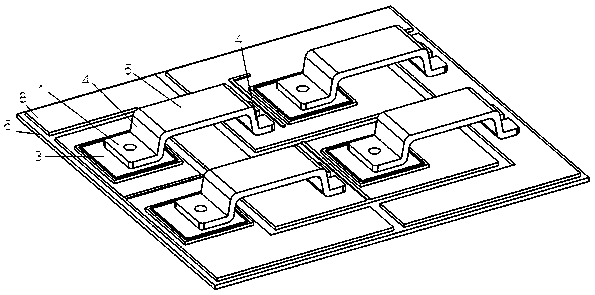
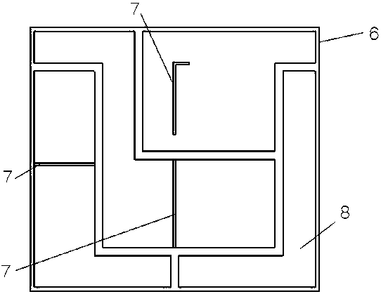
[0030] This embodiment provides a full bridge circuit, such as figure 1 , the full-bridge circuit includes a ceramic substrate 6, a copper-clad microstrip 8 and a chip 3 are provided on the ceramic substrate 6, and a copper bridge for connection is provided between the copper-clad microstrip 8 and the chip 3, and the copper bridge One end is connected to the chip 3, and the other end is connected to the copper-clad microstrip 8. The contact between the two ends of the copper bridge and the chip 3 or the copper-clad microstrip 8 is the pin mechanism 1; the copper bridge is not connected to the corresponding chip 3. The contact mechanism is divided into a suspension mechanism, and the space between the suspension mechanism and the ceramic substrate 6 is hollow.

[0031] In this embodiment: the copper connecting bridge is used to replace the connection of the aluminum wires. Compared with the parallel aluminum wires, the copper connecting bridge has a larger lateral area and a la...

Embodiment 2

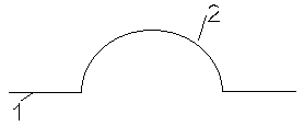
[0039] In this embodiment, the two suspended parts are arc-shaped, and the two ends of the arc are connected with the pin mechanism 1 . In detail, the suspended part 2 such as image 3 As shown, the pin mechanism 1 is arranged horizontally, and the arc part is connected with two pin mechanisms 1 . The hollow portion in the arc is used to form a hollow with the ceramic substrate 6 . Compared with the rectangle, the shape of the arc is more rounded, the gradient is small, and the sudden change is small, so that the impedance mismatch is reduced and the current loss flowing is smaller.


PUM


Abstract

The invention relates to a full-bridge circuit and a fast recovery diode, which solves the technical problem of bearing a small driving current. By adopting the full-bridge circuit, the ceramic substrate is provided with a copper-clad microstrip and a chip, and a copper-clad microstrip There is a copper bridge for connection between the strip and the chip. One end of the copper bridge is connected to the chip, and the other end is connected to the copper clad microstrip. The contact between the two ends of the copper bridge and the chip or the copper clad microstrip is the lead foot mechanism; the copper connecting bridge is not in contact with the corresponding chip and is divided into a suspension mechanism, and the technical solution of the hollow space between the suspension mechanism and the ceramic substrate solves this problem better and can be used in semiconductor module packaging.

Description

technical field [0001] The invention relates to the field of semiconductor module packaging, in particular to a full bridge circuit and a fast recovery diode. Background technique [0002] Fast recovery diode (FRD for short) is a semiconductor diode with good switching characteristics and short reverse recovery time. It is mainly used in electronic circuits such as switching power supplies, PWM pulse width modulators, and frequency converters. Freewheeling diodes or damping diodes are used. The internal structure of the fast recovery diode is different from the ordinary PN junction diode. It belongs to the PIN junction diode, that is, the base region I is added between the P-type silicon material and the N-type silicon material to form a PIN silicon chip. Because the base region is very thin and the reverse recovery charge is very small, the reverse recovery time of the fast recovery diode is short, the forward voltage drop is low, and the reverse breakdown voltage is high....

Claims


Application Information

Patent Timeline
Patent Type & Authority Patents(China)
IPC IPC(8): H01L25/07H01L23/498H01L29/861
CPCH01L23/49811H01L25/072H01L29/861H01L2224/40225
Inventor 姜季均陈飞谌容许海东
Owner 南京晟芯半导体有限公司
Why Eureka
Try Eureka