A laser additive manufacturing or remanufacturing conformal protection method and protective cover

A technology of laser additive and protective cover, applied in the field of protective cover, laser additive manufacturing or remanufacturing conformal protection, can solve the problem of not being able to meet large workpieces, etc. Effect

Active Publication Date: 2019-07-26
INST OF MECHANICS - CHINESE ACAD OF SCI +1
View PDF6 Cites 0 Cited by
  • Summary
  • Abstract
  • Description
  • Claims
  • Application Information

AI Technical Summary

Problems solved by technology

This obviously cannot meet the repair needs o

Method used


Image

  • A laser additive manufacturing or remanufacturing conformal protection method and protective cover
  • A laser additive manufacturing or remanufacturing conformal protection method and protective cover
  • A laser additive manufacturing or remanufacturing conformal protection method and protective cover

Examples


Example Embodiment

[0048] Example 1:

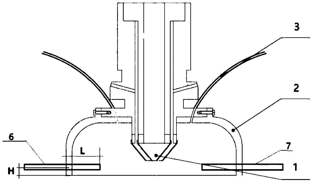
[0049] The shape of the protective cover 2 is cylindrical, with an outline of Φ700×400mm. The side and top surfaces are made of stainless steel sheets with a thickness of 0.2mm. There is an interface on the top of the cover, which can be connected to the general laser cladding head 1;

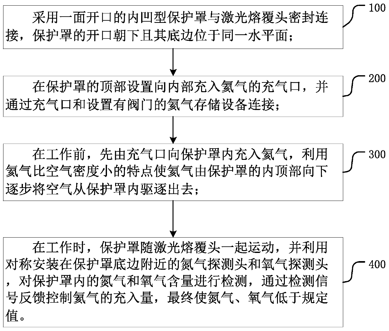
[0050] Inflate helium into the hood through the inflation tube near the top of the hood. Since helium is lower in density than air, the helium in the hood gradually expels the air and squeezes the air out from the bottom of the protective cover 2, and measures it with the probe in the protective cover 2. Oxygen and nitrogen content, so that the oxygen content is ≤100ppm, and the nitrogen content is ≤100ppm;

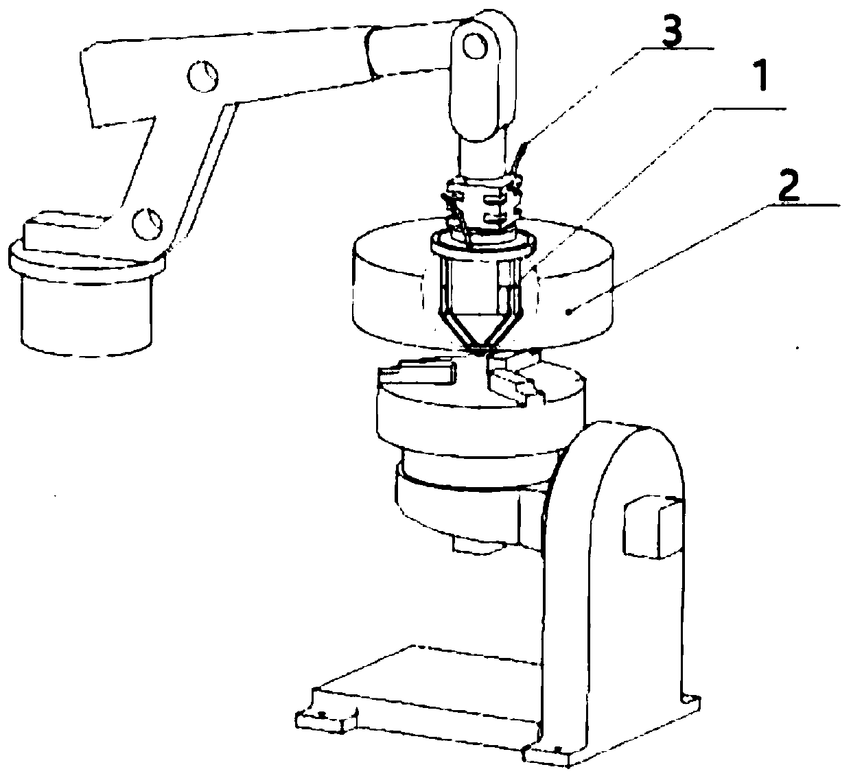
[0051] The workpiece manufactured by laser additive manufacturing will be stacked and formed on a 200mm×200mm×20mm steel plate, and the steel plate is fixed horizontally on a positioner that can tilt from -90° to +90° and rotate 360°. The working platform of the positio...

Example Embodiment

[0053] Example 2:

[0054] The shape of the protective cover 2 is bell-shaped, the bottom side is 300mm×300mm square, and the height is 200mm. The cover surface is made of flame-retardant cloth, and there is an interface on the top of the cover, which can be connected with a general laser cladding head;

[0055] Inflate helium into the hood through the inflation tube near the top of the hood. Since helium is lower in density than air, the helium in the hood gradually expels the air and squeezes the air out from the bottom of the protective cover 2, and measures it with the probe in the protective cover 2. Oxygen and nitrogen content, so that the oxygen content is ≤100ppm, and the nitrogen content is ≤100ppm;

[0056] The workpiece that needs to be remanufactured by laser is a shaft of Φ400×2000mm. The center line of the shaft is horizontal, and the two ends are fixed on the positioner and the support seat that can rotate 360°. Fasten the protective cover 2 on the side of the ...


PUM

PropertyMeasurementUnit
Heat resistance temperatureaaaaaaaaaa

Abstract

The invention provides a laser additive manufacturing or remanufacturing follow-up protection method and a protective cover. The method includes the following steps: adopting a concave protective cover with one side open and sealingly connecting it with a laser cladding head; The inflation port filled with helium inside is connected to the helium storage device with a valve through the inflation port; before work, first fill the protective cover with helium gas from the inflation port to completely expel the air from the protective cover; When working, the protective cover moves together with the laser cladding head, and the nitrogen and oxygen detection heads installed symmetrically near the bottom of the protective cover are used to detect the nitrogen and oxygen content in the protective cover, and the detection signal feedback control The filling amount of helium finally makes nitrogen and oxygen lower than the specified value. The invention can save the cabin and the vacuum unit, not only greatly reduce the cost of the equipment, reduce the weight of the equipment, but also completely change the design mode and structure of the cabin equipment, the processing space is not limited by the volume, the inflation time is short, light and flexible, and convenient for transportation .

Description

technical field [0001] The invention relates to the field of laser processing, in particular to a laser additive manufacturing or remanufacturing conformal protection method that can move with the laser cladding head so that the laser molten pool is always under the protection of helium gas, and the protection applied to the method cover. Background technique [0002] Laser additive manufacturing or laser remanufacturing technology uses laser to melt metal powder to form a molten pool on the surface of the workpiece. Driven by 3D forming software and robots, the laser molten pool is solidified point by point and accumulated layer by layer. Due to the high melting point of metal materials, in order to avoid oxidation and nitriding, the laser melting pool must be isolated from the air and placed in an inert gas protection environment. At present, the complete sets of laser additive manufacturing / remanufacturing equipment generally adopt a cabin structure, and the subsystems s...

Claims


Application Information

Patent Timeline
IPC IPC(8): B22F3/105B33Y10/00B33Y30/00
CPCB22F3/003B33Y10/00B33Y30/00B22F2999/00B22F10/00B22F12/90B22F10/28B22F12/70B22F10/32B22F2201/12Y02P10/25
Inventor 李正阳董世运蒋华臻闫世兴彭青高欢
Owner INST OF MECHANICS - CHINESE ACAD OF SCI
Why Eureka
Try Eureka