Air micro-cavity type fiber hydrophone, manufacturing method of the same, and signal detection method

A fiber optic hydrophone and signal detection technology, applied in instruments, measuring devices, measuring ultrasonic/sonic/infrasonic waves, etc., can solve the problems of reducing the applicability and flexibility of the sensor, difficult to guarantee the repeatability of the sensor, and high process requirements. , to overcome the lack of repeatability of device structure parameters, reduce the difficulty of manufacturing, and avoid the process of

Active Publication Date: 2018-03-20
JINAN UNIVERSITY
View PDF15 Cites 10 Cited by
  • Summary
  • Abstract
  • Description
  • Claims
  • Application Information

AI Technical Summary

Problems solved by technology

Therefore, at present most of the optical fiber Fabry-Perot hydrophones are based on the elastic diaphragm deformation caused by the detection pressure (invention patent CN103091013, "miniature SU-8 optical fiber Fabry-Perot pressure sensor and preparation method"; invention patent CN101858809 , "An optical fiber Fabry-Perot pressure sensor and its preparation method"; invention patent CN102384809, "High-stability Fabry-Perot pressure sensor without glue packaging and its preparation method"). The process of making a hollow cavity on the end face of an optical f

Method used


Image

  • Air micro-cavity type fiber hydrophone, manufacturing method of the same, and signal detection method
  • Air micro-cavity type fiber hydrophone, manufacturing method of the same, and signal detection method
  • Air micro-cavity type fiber hydrophone, manufacturing method of the same, and signal detection method

Examples


Embodiment 1

[0035] This embodiment firstly discloses an air microcavity fiber optic hydrophone, which includes an optical fiber whose end surface is coated with a light-absorbing material and an air microcavity generated by optical heating on the end surface of the optical fiber.

[0036] Using the air microcavity fiber optic hydrophone of this embodiment, an air microcavity is generated at the fiber end face by an optical heating method to form a Fabry-Perot interferometer, wherein the fiber end face / air microcavity and the air microcavity / liquid two The reflected light from the two interfaces interferes to form interference fringes. When the air microcavity is subjected to external pressure, its cavity length will change, and the change of reflection spectrum interference fringes will be manifested in the form of optical path difference change. By detecting the wavelength shift of the interference spectrum, the measurement of the external pressure is realized. Since the air microcavity...

Embodiment 2

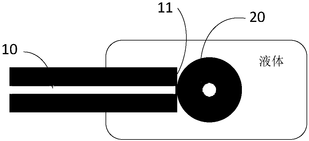
[0046] This embodiment discloses an air microcavity fiber optic hydrophone. see figure 1 , figure 1 It is the structural schematic diagram of the air microcavity fiber optic hydrophone of the present embodiment, the air microcavity fiber optic hydrophone of the embodiment of the present invention, comprises the transmission optical fiber 10, the air microcavity 20 that has end face plated with light absorbing material 11; Wherein , the transmission optical fiber 10 is immersed in the liquid, the air microcavity 20 is located at the center of the fiber end face, and the air microcavity 20 constitutes a Fabry-Perot cavity. The interface between the end face of the transmission fiber 10 and the air microcavity 20 and the interface between the air microcavity 20 and the liquid are two reflection surfaces of the Fabry-Perot cavity.

[0047] The air microcavity 20 in the above-mentioned sensor is easy to process and is located at the center of the end face of the transmission opti...


PUM


Abstract

The invention discloses an air micro-cavity type fiber hydrophone, a manufacturing method of the same, and a signal detection method. The air micro-cavity type fiber hydrophone is formed by a fiber and an air micro-cavity at the end surface of the fiber, wherein the air micro-cavity can be used as a compressible Fabry-Perot cavity for sensing the micro-cavity length or reflected light interferencespectrum change caused by the external pressure so as to realize measurement of sound wave and ultrasonic wave. The manufacturing method of the air micro-cavity type fiber hydrophone is simple, and optically heats the fiber end surface coated with luminous absorption material to realize water vaporization on the fiber end surface and form an air micro-cavity on the fiber end surface, thus avoiding the complicated process, such as fiber Fabry-Perot cavity structure manufacturing and pressure sensitive film welding. Besides, the manufacturing method of the air micro-cavity type fiber hydrophonerealizes accurate on-line control of the cavity length by adjusting the heating laser power, can overcome the problem that a traditional manufacturing method is not enough in the repeatability of device structural parameters, can realize dynamic tuning of the measurement range and the working frequency band on single sensor, and can improve applicability of the sensor.

Description

technical field [0001] The invention relates to the technical field of pressure measuring devices, in particular to an air microcavity optical fiber hydrophone, a manufacturing method and a signal detection method. Background technique [0002] The optical fiber Fabry-Perot optical fiber sensor has simple structure and accurate detection. It is a common type of optical fiber hydrophone. When the elastic diaphragm in the Fabry-Perot cavity is on the diaphragm, the diaphragm will be deformed, thereby changing the cavity length of the Fabry-Perot cavity. By detecting the change of the reflected light interference spectrum caused by the change of the cavity length, it can be realized Measurement of sound waves and ultrasound. Therefore, at present most of the optical fiber Fabry-Perot hydrophones are based on the elastic diaphragm deformation caused by the detection pressure (invention patent CN103091013, "miniature SU-8 optical fiber Fabry-Perot pressure sensor and preparation...

Claims


Application Information

Patent Timeline
IPC IPC(8): G01H9/00
Inventor 马军许洪松金龙关柏鸥
Owner JINAN UNIVERSITY
Why Eureka
Try Eureka