New electric automobile charging circuit and control method thereof

A charging circuit, electric vehicle technology, applied in electric vehicle charging technology, electric vehicles, battery circuit devices, etc., can solve problems such as low efficiency, low power density, insufficient power factor, etc., to ensure reliability, reduce volume, The effect of reducing the amount of use

Inactive Publication Date: 2018-03-23
SOUTHEAST UNIV
View PDF8 Cites 5 Cited by
  • Summary
  • Abstract
  • Description
  • Claims
  • Application Information

AI Technical Summary

Problems solved by technology

At present, some chargers still use a more traditional structure, simply connecting the charging interface, bidirectional AC / DC converter, bidirectional DC / DC converter and power battery in series, which has disadvantages such as low efficiency, insufficient power factor, and low energy density.
Patent CN106647332A provides a design method for two-way charging and discharging of automobiles, which can realize two-way power transmission, and can effectively suppress harmonics to ensure power factor, but lacks an electrical isolation module, making it difficult to ensure the safety of users and equipment
Patent CN102222958A provides a vehicle-mounted bidirectional charger for electric vehicles, which uses an isolated dual-active half-bridge bidirectional DC / DC converter to make the conversion performance more efficient and stable, but the charging rate is low and cannot meet the increasing charging speed need
Patent CN102983606A discloses a bidirectional charging system for electric vehicle charging, which is composed of multiple bidirectional AC / DC and DC / DC modules, which improves the adjustable charging and discharging power, and can realize bidirectional transmission of electric energy with high power. However, due to the use of more converter modules, the volume is larger, the power density is lower, and the cost is higher

Method used


Image

  • New electric automobile charging circuit and control method thereof
  • New electric automobile charging circuit and control method thereof
  • New electric automobile charging circuit and control method thereof

Examples


Embodiment 1

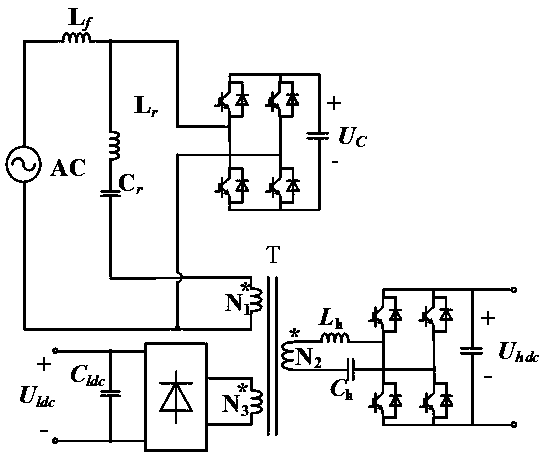
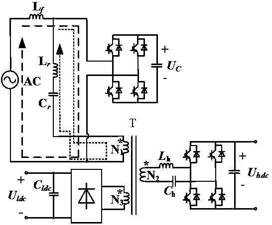
[0025] Embodiment 1: as figure 1 As shown, the electric vehicle charging circuit of the present invention is composed of a control unit and sequentially connected charging input terminals, PWM rectifiers, energy storage capacitors, resonant circuits, high-frequency isolation transformers, high-voltage rectifying and filtering circuits, low-voltage rectifying and filtering circuits, low-voltage output terminals and The charging output terminal constitutes. Due to the existence of the series resonant circuit, the charging circuit on the primary side of the high-frequency isolation transformer is divided into a power frequency circuit and a high-frequency circuit, such as figure 2 As shown, the frequency of the high-frequency circuit is the resonant frequency of the series resonant circuit, and its value is greater than the power frequency and less than the switching frequency. In this example, it is selected as 15kHz.

[0026] The power frequency is 220V, 50Hz power supply cha...

Embodiment 2

[0031] Such as Figure 5 As shown, the control of the PWM rectifier adopts the double closed-loop control strategy of the voltage outer loop and the current inner loop, and the energy storage capacitor voltage U c As the control object of the voltage outer loop, the current in the power frequency circuit i ac As the control object of the current inner loop, the modulated wave signal is obtained through PI adjustment and coordinate transformation, and a high-frequency sine signal or square wave signal is superimposed on the obtained modulated wave signal. The frequency of the signal is the same as the resonant frequency of the resonant circuit. equal to f h , and the frequency is greater than the power frequency and less than the switching frequency. At the same time, the output voltage U hdc As the control object, after PI adjustment, the amplitude of the sine signal or square wave signal superimposed on the modulation wave signal is controlled.

[0032] The specific i...

Embodiment 3

[0041] Such as Figure 7 As shown, the power frequency grid side, high-voltage DC side and low-voltage DC side can have multiple working states, such as grid-connected charging, grid-connected charging-low-voltage power supply, off-grid low-voltage power supply, and grid-connected reverse charging.

[0042] Turn off the low-voltage rectification and filtering circuit, connect the charging circuit to the grid to obtain power, and the secondary side of the high-frequency transformer supplies power to the battery through the high-voltage rectification and filtering circuit. empty state.

[0043] The charging circuit is connected to the grid to obtain power. The secondary side of the high-frequency transformer supplies power to the battery through the high-voltage rectification and filtering circuit. Charging - the working state of low-voltage power supply.

[0044] The input end of the charging circuit is not connected to the power grid. When the high-voltage rectifier circuit ...


PUM


Abstract

The invention relates to a new electric automobile charging circuit and a control method thereof. The topological structure of the new electric automobile charging circuit comprises an industrial frequency alternating current level, a PWM rectifier, a high frequency isolation transformer, a high voltage rectification filter circuit, a low voltage rectification filter circuit and a direct current output end. The industrial frequency alternating current level is controlled by using a double closed loop control strategy which consists of an outer voltage loop and an inner current loop to output direct current voltage to charge an energy-storage capacitor. According to the technical scheme of the new electric automobile charging circuit, the PWM rectifier adopts a switching tube full bridge structure; and meanwhile, functions such as a power factor correction function, industrial frequency rectification function, high frequency inversion function and so on are realized; therefore, the usenumber of switching tubes is greatly reduced. The industrial frequency current is cut off by using a series resonance circuit and energy is provided to the high frequency isolation transformer by using high frequency current generated by the PWM rectifier; therefore, the volume of the transformer can be effectively reduced.

Description

technical field [0001] The invention relates to a novel electric vehicle charging circuit and a control method thereof, belonging to the technical field of electric vehicle charging. Background technique [0002] With the development of modern high-tech and the increasingly prominent problems of environment and energy in today's world, electric vehicles have become the focus of the automotive industry due to their superior environmental protection characteristics. With the promulgation of a number of national support policies for new energy vehicles, the pace of development of new energy vehicles is accelerating, and the pace of construction of charging infrastructure is also accelerating. At present, some chargers still use a more traditional structure, simply connecting the charging interface, bidirectional AC / DC converter, bidirectional DC / DC converter and power battery in series, which has disadvantages such as low efficiency, insufficient power factor, and low energy ...

Claims


Application Information

Patent Timeline
Patent Type & Authority Applications(China)
IPC IPC(8): B60L11/18H02J7/04H02M3/335
CPCB60L53/60H02J7/045H02M3/3353H02M3/33561Y02T10/70Y02T10/7072Y02T10/72Y02T90/12
Inventor 陈武宋展飞
Owner SOUTHEAST UNIV
Why Eureka
Try Eureka