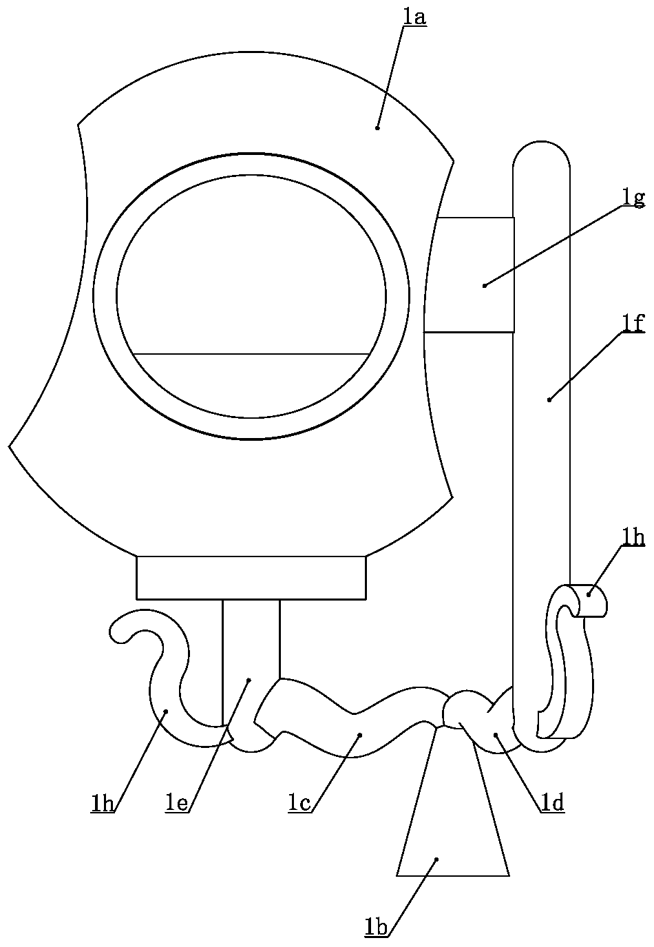
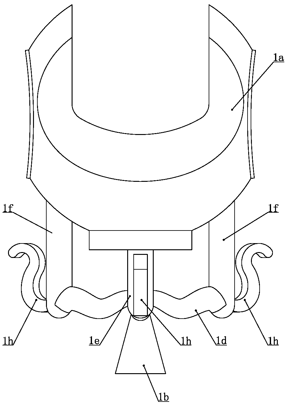
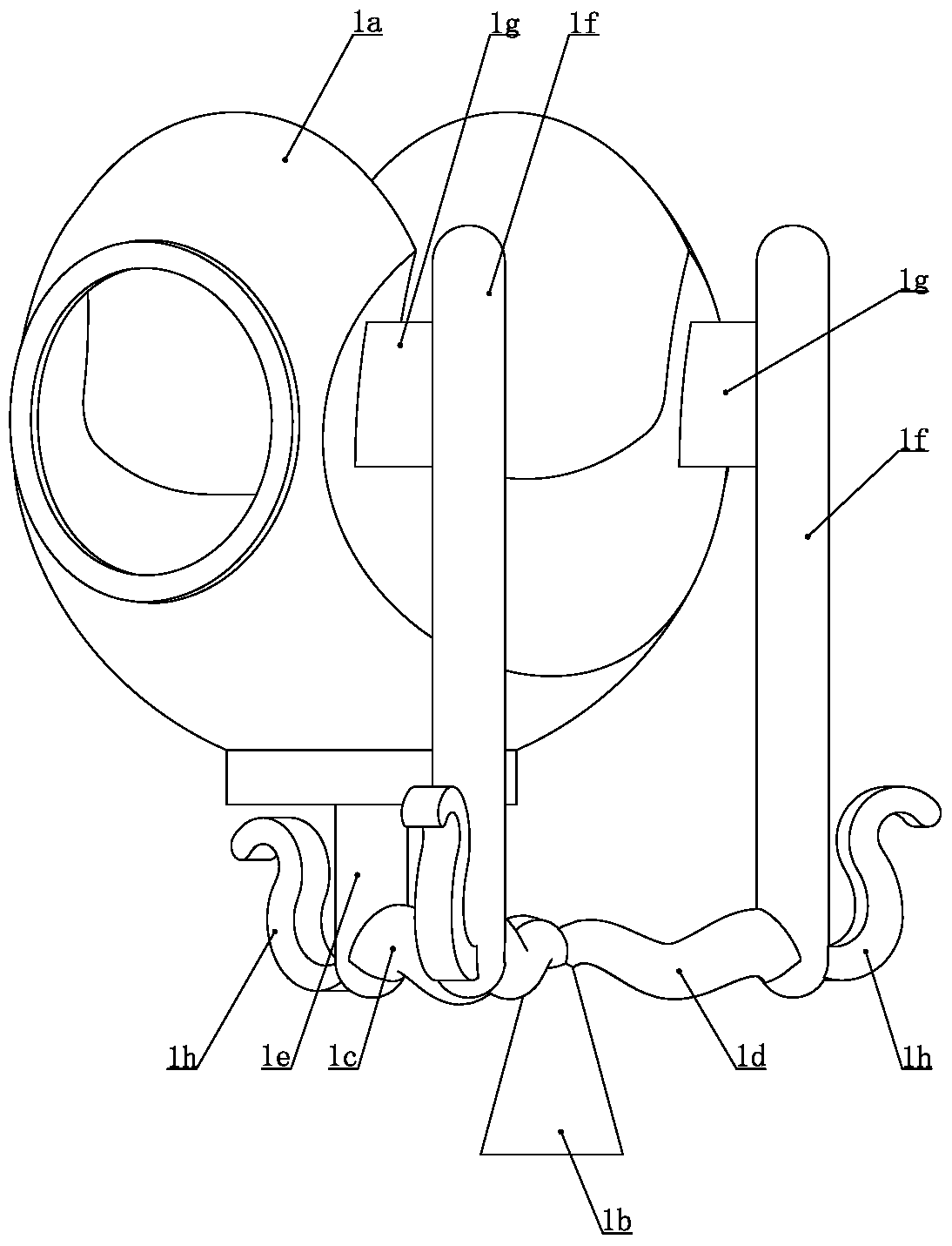
Investment casting system and method for U-shaped magnesium alloy parts
A technology of investment casting and magnesium alloy, which is applied in the field of investment casting of U-shaped magnesium alloy parts, casting of magnesium alloy parts, and investment casting system of U-shaped magnesium alloy parts. Reduce, shrinkage cavity and other problems, achieve the effect of reducing the occurrence of porosity and secondary oxidation, over-speed and over-flow of buffer magnesium solution, and reducing secondary oxidation slag
- Summary
- Abstract
- Description
- Claims
- Application Information
AI Technical Summary
Problems solved by technology
Method used
Image
Examples
Embodiment 1
[0041]The investment casting method of U-shaped magnesium alloy part of the present invention, comprises the following steps successively: (1) respectively make the profile mold of U-shaped workpiece model and the core box mold that is used to make core, and described profile mold comprises symmetrical upper mold and lower mold mold, the mold cavity of the upper mold and the lower mold can be enclosed to form the shape of the U-shaped workpiece model; (2) the soluble material is injected into the core box mold under high pressure, and after cooling and shaping, it is taken out from the core box mold to obtain a soluble core; (3) The dissolvable core is placed in the mold cavity of the shape mould, the upper mold and the lower mold are combined and locked; (4) the mold material required for making the U-shaped workpiece model is configured in the wax melting machine, and the mold The material is injected into the mold cavity of the shape mold; (5) After the mold material is cool...
Embodiment 2
[0060] All the other steps are identical with embodiment one, the structure of the liquid riser 21 that adopts is different, as Figure 7 to Figure 13 As shown, in step ⒀, the lower port of the riser pipe 21 is closed, and the circumference of the lower end of the riser pipe 21 is provided with a riser pipe inlet 21a, and the riser pipe inlet 21a is provided with a Pneumatic valve 21f with liquid port closed or opened, a pneumatic valve cavity 21d that can accommodate the pneumatic valve 21f is provided on the circumference of the rising tube on the side of the liquid inlet 21a of the rising tube, the liquid inlet 21a of the rising tube and the pneumatic valve cavity 21d The upper and lower ends of the upper and lower ends are respectively provided with door rails 21e for the sliding of the pneumatic valve 21f, the upper and lower ends of the inner end of the pneumatic valve cavity 21d are respectively fixedly connected with extension springs 21g, and the other ends of the exte...
PUM
 Abstract
Description
Claims
Application Information
 - R&D
- Intellectual Property
- Life Sciences
- Materials
- Tech Scout
- Unparalleled Data Quality
- Higher Quality Content
- 60% Fewer Hallucinations
Browse by: Latest US Patents, China's latest patents, Technical Efficacy Thesaurus, Application Domain, Technology Topic, Popular Technical Reports.
© 2025 PatSnap. All rights reserved.Legal|Privacy policy|Modern Slavery Act Transparency Statement|Sitemap|About US| Contact US: help@patsnap.com


