

Catalytic combustion and inerting aircraft fuel tank system with gas supplement, and control method
A technology for fuel tanks and aircraft, applied in the direction of fuel tank safety measures, etc., can solve the problems of environmental pollution, low efficiency of hollow fiber membrane nitrogen production, high price, etc., achieve simple process, high inertization efficiency, and shorten the time required for inertization Effect
- Summary
- Abstract
- Description
- Claims
- Application Information
AI Technical Summary
Problems solved by technology
Method used
Image

Examples
Embodiment 2
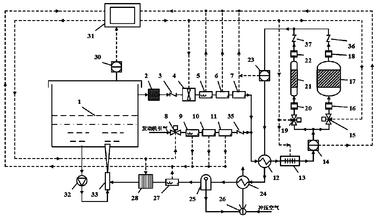
[0058] This embodiment adopts injector washing and inerting, and this system is applied to fuel washing of aircraft fuel tanks or ground fuel tanks, such as figure 2 As shown, the fuel tank 1 is an oil storage tank container, and the lower part of the fuel tank 1 is provided with a washing injector 33, and an oil pump 32 is connected through a pipeline between the fuel outlet at the bottom of the fuel tank 1 and the fuel liquid inlet of the washing injector 33, and the washing injector 33 is in the Below the lowest liquid level at the bottom of fuel tank 1.
[0059] The working process is as follows:
[0060] The inert gas mixture with low water content exiting from the gas outlet of the water separator 25 is sent into the scrubber injector 33, and after being mixed with the fuel from the bottom of the fuel tank 1, flows from the outlet of the scrubber injector 33 In the fuel in the fuel tank 1, the oxygen content in the fuel is reduced, and the mixed gas is below the explos...
Embodiment 3
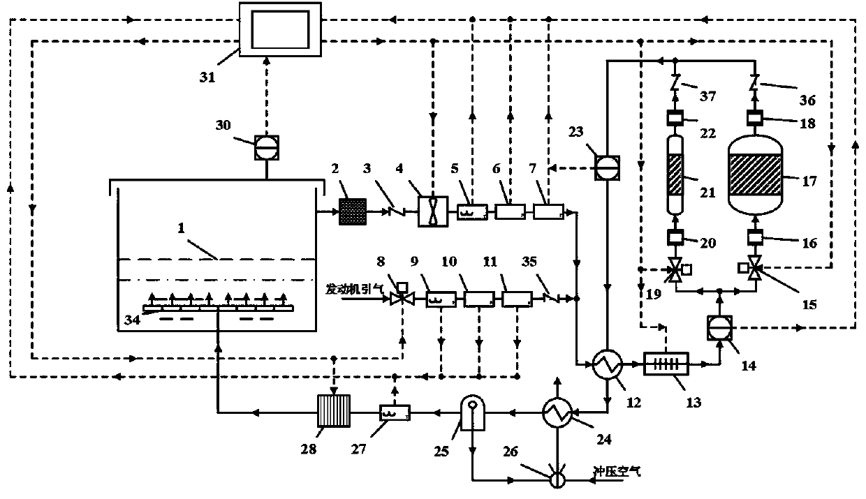
[0062]In this embodiment, the dispenser is used to wash the inerted fuel tank, and the system is applied to fuel washing of aircraft fuel tanks or ground fuel tanks, such as image 3 As shown, a gas distributor 34 is placed inside the oil in the oil tank 1 , and the outlet of the gas distributor 34 is below the lowest liquid level at the bottom of the oil tank 1 .
[0063] The working process is as follows:
[0064] The low water content inert mixed gas leaving the gas outlet of the water separator 25 is sent into the gas distributor 34, and the gas distributor 34 is arranged in the oil in the oil tank 1, and the low water content inert mixed gas is distributed from the gas The outlet of the device 34 flows into the fuel oil in the fuel tank 1, the oxygen content in the fuel oil is reduced, and the mixed gas is below the explosion limit, so as to achieve the purpose of inertization.
PUM
 Abstract
Description
Claims
Application Information