Sectional type pyrolysis and gasification device

A pyrolysis gasification, segmented technology, applied in the direction of gasification device feeding tools, gasification process, chemical industry, etc., can solve the problems of uneven air distribution of materials, high energy consumption, low biomass conversion rate, etc. , to achieve the effect of prolonging the reaction residence time, improving the pyrolysis efficiency, and uniform and stable reaction

Pending Publication Date: 2018-04-13
常州至拓新能源开发有限公司
View PDF0 Cites 2 Cited by
  • Summary
  • Abstract
  • Description
  • Claims
  • Application Information

AI Technical Summary

Problems solved by technology

Due to high energy consumption, low heat transfer efficiency and low biomass conversion rate, dry distillation process is generally used in charcoal production process
The fixed bed gasification process mainly includes updraft gasifier, downdraft gasifier, and mixed suction gasifier, etc. The material in the fixed bed naturally accumulates, and due to the inhomogeneity of the material and the inhomogeneity of the air distribution, resulting in Local over-burning and under-burning are prone to occur in the furnace, resulting in a series of problems such as low reaction rate and coking in the furnace, which seriously restrict the stable operation and large-scale development of the fixed-bed gasifier
Among t

Method used


Image

  • Sectional type pyrolysis and gasification device
  • Sectional type pyrolysis and gasification device
  • Sectional type pyrolysis and gasification device

Examples


Example Embodiment

[0021] Example 1 of double-axis double-return

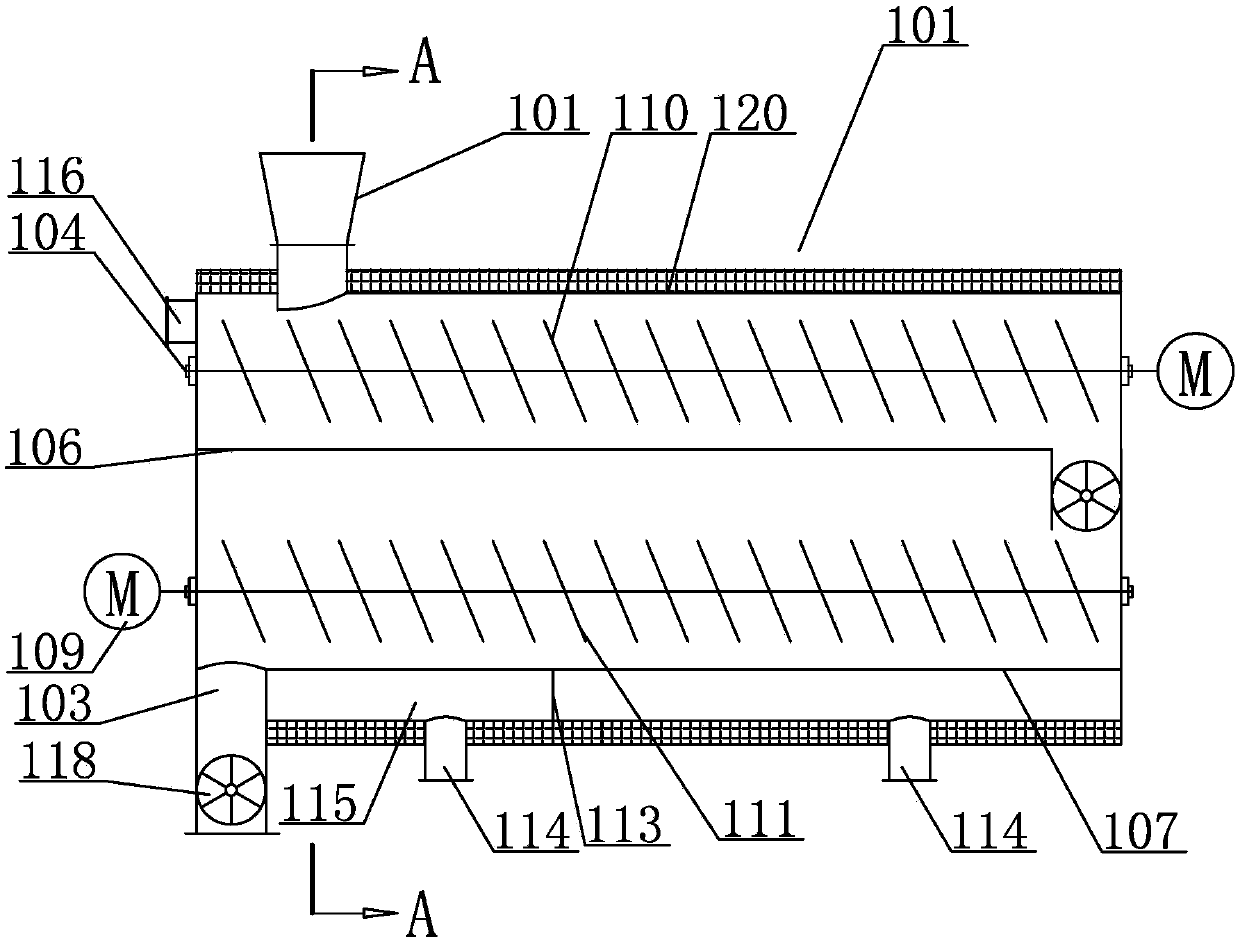
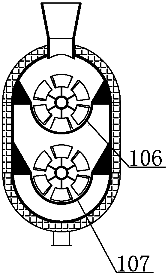
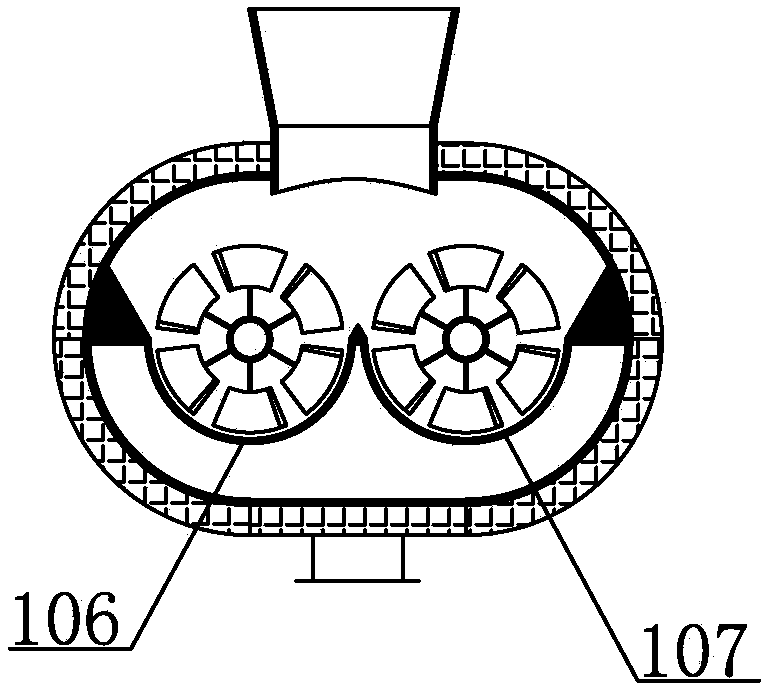
[0022] like Figure 1-5 As shown, a segmented pyrolysis gasification device includes a first furnace body 101, a first feed port 102 and a first discharge port 103 provided on the first furnace body 101, and a first furnace body Inside 101, there are two first main shafts 104 and second main shafts 105 that are spaced apart and cross the first furnace body 101, and a first trough-type air distribution plate 106 is provided below the first main shaft 104 and the second main shaft 105. and the second trough air distribution plate 107, the first drive governor 108 and the second drive governor 109 respectively provided on the first main shaft 104 and the second main shaft 105, the first main shaft 104 and the second main shaft 105 are respectively provided with a plurality of first blades 110 and second blades 111 distributed at equal intervals, a second outlet 112 provided on one side of the first trough-type air distribution plat...

Example Embodiment

[0023] Embodiment 2 of segmented spiral pyrolysis gasifier

[0024] like Image 6 As shown, a segmented pyrolysis and gasification device includes three first spiral pyrolysis and gasification furnaces 210, second spiral pyrolysis and gasification furnaces 220 and third spiral pyrolysis and gasification furnaces 230 connected in series. . The first spiral pyrolysis gasification furnace 210 includes a second furnace body 211, a second feed port 212 and a third discharge port 213 provided on the second furnace body 211, and a horizontal Pass through the third main shaft 214 of the second furnace body 211, the third trough type air distribution plate 215 provided on the third main shaft 214, the third drive governor 216 provided on the third main shaft 214, The three main shafts 214 are provided with a plurality of third blades 217 distributed at equal intervals, and the second partition plate 218 and the corresponding third trough type air distribution plate 215 and the inner ...

Example Embodiment

[0025] Example 3 of the process principle of obtaining high calorific value and low tar gas in a segmented spiral pyrolysis gasifier

[0026] like Figure 7 As shown, the material enters the system from the feed port of the first spiral pyrolysis gasifier 210 in the reaction section, and is dried and pyrolyzed in the first spiral pyrolysis gasifier 210 in the reaction section, and the gas is heated by the first spiral pyrolysis gasifier in the reaction section. The second gas outlet 240 of the pyrolysis gasifier 210 is discharged, and in the second spiral pyrolysis gasifier 220 of the reaction section, the air entering through the third gasification agent inlet 229 is mixed with the air from the first spiral pyrolysis gasifier 210 of the reaction section. The material in the third discharge port 213 undergoes a gasification reaction to generate gas and release heat, which is used to maintain the high temperature environment of the second spiral pyrolysis gasifier 220 in the re...


PUM


Abstract

The invention discloses a sectional type pyrolysis and gasification device, which comprises a first furnace body, a first feeding hole, a first discharging hole, a first main shaft, a second main shaft, a first groove-type air distribution board, a second groove-type air distribution board, a first driving speed controller, a second driving speed controller, a plurality of first blades, a plurality of second blades, a second discharge hole, a first clapboard and a first gasification agent inlet, wherein the plurality of first blades and the plurality of second blades which are distributed at equal intervals are respectively arranged on the first main shaft and the second main shaft; the second discharge hole is arranged on one side of the first groove-type air distribution board; the firstclapboard is arranged between the second groove-type air distribution board and the inner wall of the furnace body; the first gasification agent inlet is arranged on the furnace body of one side of the corresponding second groove-type air distribution board; the first furnace body is provided with a first fuel outlet. The sectional type pyrolysis and gasification device has high pyrolysis efficiency and stable and even reaction, heat exchange efficiency is improved, reaction remaining time is prolonged, handling capacity is improved, investment cost is saved, and an effect on greatly saving separation, refining and purification cost in a subsequent production utilization process can be realized.

Description

technical field [0001] The invention relates to the field of thermochemical conversion of biomass solid waste, in particular to a segmented pyrolysis gasification device. Background technique [0002] As one of the technical approaches of biomass thermochemical conversion, biomass pyrolysis gasification technology is a conversion method that is cleaner and more efficient than direct combustion. Under the condition of high temperature and oxygen deficiency, biomass is converted into combustible gas, liquid mixture and Solid carbon, the product is determined by different process conditions, and the product can be used for power generation and heat supply, synthetic fuel and chemicals, etc. The core equipment of this technology is a pyrolysis gasification reactor. At present, the mainstream equipment for engineering application is fixed bed and fluidized bed, each of which includes different forms. The fixed bed has the advantages of simple structure, low manufacturing cost, a...

Claims


Application Information

Patent Timeline
IPC IPC(8): C10J3/72
CPCC10J3/72C10J3/721C10J2200/15C10J2300/1207C10J2300/0916C10J2300/1603Y02P20/10
Inventor 曹鹏其他发明人请求不公开姓名
Owner 常州至拓新能源开发有限公司
Why Eureka
Try Eureka