Jet-based micro-bubble generation method and jet micro-bubble aerator

A method for generating microbubbles, applied in water aeration, chemical instruments and methods, sustainable biological treatment, etc., can solve the problems of large bubble volume, low oxygen utilization rate, poor mixing uniformity, etc., to increase the total contact area, increase the contact area, and reduce the effect of the bubble diameter

Active Publication Date: 2018-04-17
NANJING UNIV OF AERONAUTICS & ASTRONAUTICS
View PDF4 Cites 16 Cited by
  • Summary
  • Abstract
  • Description
  • Claims
  • Application Information

AI Technical Summary

Problems solved by technology

[0006] The purpose of the present invention is to overcome the disadvantages of large bubble volume, poor mixing uniformity, and low oxygen utilization rate produced by traditional aerator gas, and provide a jet-based microbubble generation method and a jet microbubble aerator using the method ,

Method used


Image

  • Jet-based micro-bubble generation method and jet micro-bubble aerator
  • Jet-based micro-bubble generation method and jet micro-bubble aerator
  • Jet-based micro-bubble generation method and jet micro-bubble aerator

Examples


Example Embodiment

[0054] Example 1

[0055] 1. Use environment and parameters

[0056] This application example is a jet microbubble aerator for sewage treatment, in which the volume flow rate of sewage is 13m 3 / h, according to the relevant requirements of sewage treatment, the gas-liquid volume flow ratio is 0.1.

[0057] 2. Program introduction

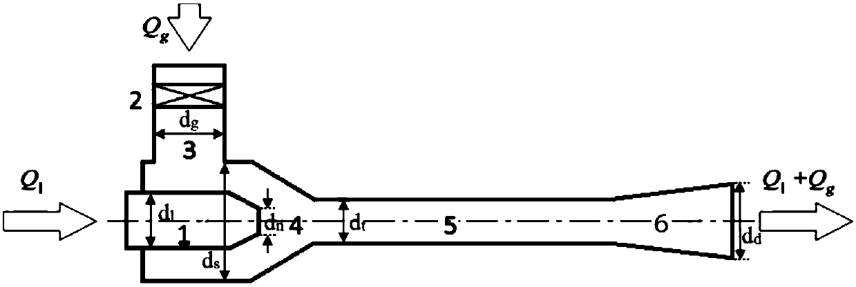
[0058] Combine Figure 5 with Image 6 , The jet microbubble aeration device designed according to the prior art, the design parameters closely related to the present invention are: the diameter of the inlet pipe Where Q l Is the liquid flow, u l1 Design flow rate for liquid; nozzle diameter Where φ is the nozzle velocity coefficient, P l Is the liquid flow rate, ρ is the fluid density; the length of the nozzle of the inlet pipe shrinks L n =a n (d l -d n ), where a n Is the nozzle contraction length coefficient; intake pipe diameter Where q is the gas-liquid flow ratio, u g2 Design flow rate for gas; suction chamber diameter d s =a ds d l , Where a ds Is...


PUM


Abstract

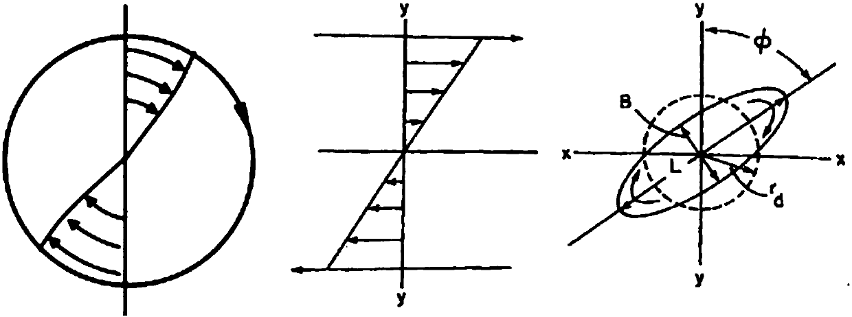
The invention relates to a jet-based micro-bubble generation method and a jet micro-bubble aerator. The aerator comprises a water inlet pipe, an air inlet pipe, an air suction chamber, a throat pipe section, and a diffusion pipe section, wherein a nozzle is connected to the water inlet pipe, the nozzle extends into the air suction chamber, and the air inlet pipe is also connected to the air suction chamber; the air suction chamber is a closed chamber, which comprises an outlet, the outlet is connected to the throat pipe section, the throat pipe section is connected to the diffusion pipe section, and ultimately, the diffusion pipe section extends into an external aeration device. Because the shear rate of a flow field at the position of the nozzle and/or in the throat pipe section is greater than the critical shear rate of big bubble breaking when the aerator is used, the geometrical shape of the jet micro-bubble aerator can be determined. The micro-bubble aerator has the advantages ofsimple structure, low cost, no blockage and convenience in repair; by the jet micro-bubble generation method, a large quantity of tiny bubbles can be continuously generated, the oxygen utilization rate is increased, and the energy consumption and cost of water treatment are reduced.

Description

technical field [0001] The present invention relates to a method and technology for generating micro-bubbles in a liquid (water body), application of aeration technology and other fields, especially the fields of sewage treatment and chemical industry, and specifically relates to a jet micro-bubble generation method and a jet micro-bubble aerator . Background technique [0002] The mutual contact between gas phase and liquid phase is a very common and important operation in sewage treatment process, flotation and chemical reaction process, and it is also the basic process of gas-liquid two-phase mass transfer. Typically, this is done by dispersing the gas phase into the liquid phase in the form of gas bubbles. In the process of chemical reaction and sewage treatment, the degree of full contact between the gas phase and the liquid phase (contact area, bubble surface area) often determines the speed and quality of the reaction. Therefore, how to fully dissolve the gas (gas p...

Claims


Application Information

Patent Timeline
IPC IPC(8): C02F7/00
CPCC02F7/00Y02W10/10
Inventor 孙建红
Owner NANJING UNIV OF AERONAUTICS & ASTRONAUTICS
Why Eureka
Try Eureka