Electronic injection flash boiler for supercritical pyrolysis gas

A technology for pyrolysis gas and flash boilers, which is applied to steam generators, thermal decomposition condensation reduction equipment, and boiler fields, can solve the problems of unclear material classification, long extraction process time, and high investment costs, and achieves expansion Heat exchange area, improved thermal efficiency, low exhaust gas temperature

Inactive Publication Date: 2018-04-20
广东欣鑫华能环保科技有限公司
View PDF4 Cites 6 Cited by
  • Summary
  • Abstract
  • Description
  • Claims
  • Application Information

AI Technical Summary

Problems solved by technology

[0003] In order to solve the problems of high energy consumption, high investment cost, long extraction process time and unclear classification of substances in the process ...

Method used


Image

  • Electronic injection flash boiler for supercritical pyrolysis gas
  • Electronic injection flash boiler for supercritical pyrolysis gas

Examples


Embodiment Construction

[0045] The present invention will be further described below in conjunction with the accompanying drawings and specific implementation.

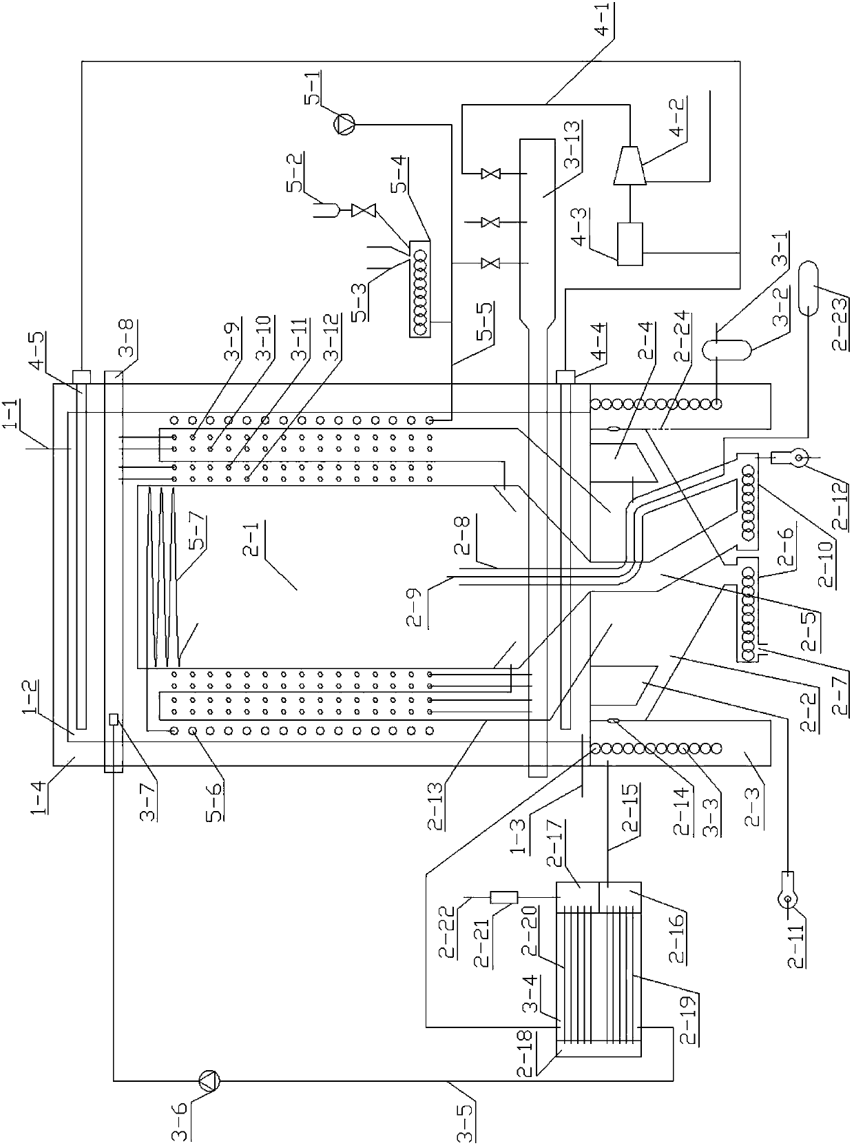
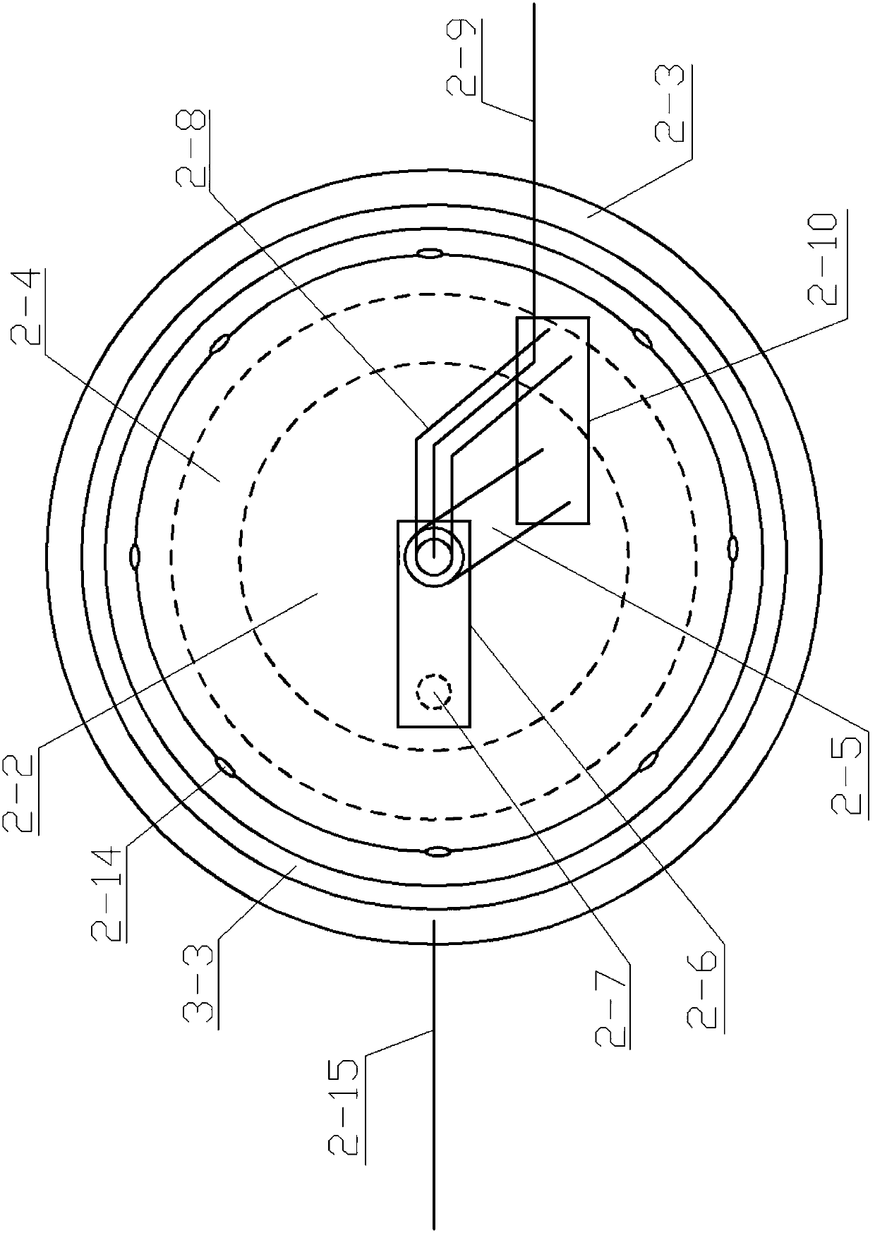
[0046] The supercritical steam colliding material thermal decomposition boiling range condensation reduction separation equipment structure of the present invention is as follows figure 1 , figure 2 As shown, the supercritical pyrolysis gas electric injection flash boiler consists of molten salt feeding pipe 1-1, molten salt tank 1-2, molten salt discharge pipe 1-3, insulation layer 1-4, combustion chamber 2-1, smoke Air pipe 2-2, flue gas chamber 2-3, burner 2-4, waste heat recovery water tank 3-1, water outlet pipe 3-2, high-pressure plunger pump 3-3, high-pressure spray device 3-4, steam generator 3-5, steam coil 3-6, steam tank 3-7, sub cylinder 3-8, smoke exhaust pipe 3-9, water inlet pipe 3-10, first flue gas tank 3-11, second flue gas tank 3-12, third flue gas tank 3-13, air pipe 3-14, water tank 3-15, steam turbine 4-1, generator ...


PUM


Abstract

The invention discloses an electronic injection flash boiler for supercritical pyrolysis gas. The electronic injection flash boiler for the supercritical pyrolysis gas is composed of a fused salt adding pipe, a fused salt groove, a fused salt discharge pipe, a heat-insulation layer, a combustion cavity, a smoke pipe, a smoke cavity, a combustor, a waste heat recovery water tank, a water outlet pipe, a high-pressure plunger pump, a high-pressure spraying device, a steam generator, a steam coiled pipe, a steam groove, a steam distribution cylinder, a smoke discharge pipe, a water inlet pipe, a first smoke groove, a second smoke groove, a third smoke groove, an air pipe, a water groove, a steam turbine, a power generator, a first electric heater, a second electric heater, a solid material conveyer, a liquid material conveyer, a steam collision substance decomposition coiled pipe, a vertical separation tower, a horizontal decomposition chamber, a circulation water pump and a cooling tower.The invention provides a substance thermal decomposition and separation device which is simple in structure, efficient and energy-saving, high in heat conversion efficiency, large in heat exchange area, complete in substance classification, adequate in decomposition, clear in separation, high in collection speed, convenient to operate, capable of realizing waste heat utilization, and free from emission.

Description

technical field [0001] The invention relates to a boiler, a steam generator, and thermal decomposition condensation reduction separation equipment. Specifically, it is a supercritical steam collision material thermal decomposition boiling range condensation reduction separation device. Background technique [0002] With the continuous and rapid development of the requirements for material concentration, distillation, drying, extraction and refining in the industrial development, higher requirements are put forward for the concentration, distillation, drying, extraction and refining equipment. The traditional concentration, distillation, drying, Extraction and refining equipment are complex in process, bulky and bulky, high in investment cost, labor intensive, and energy consuming, which can no longer meet the needs of current industrialized mass production. The present invention improves and upgrades the original solar oil heat conduction heating device, thermal radiation i...

Claims


Application Information

Patent Timeline
IPC IPC(8): F22B1/06F22B1/28C10B53/00
CPCC10B53/00F22B1/06F22B1/28Y02P20/129
Inventor 赖正平石雄伟甘军农成莫林郑继友
Owner 广东欣鑫华能环保科技有限公司
Why Eureka
Try Eureka