Preparation method of diaphragm, electrode and current collector integrated structure as well as preparation method of battery

A technology of current collectors and diaphragms, applied in structural parts, battery pack parts, separators/films/diaphragms/spacers, etc., to achieve the effect of enhancing bonding force, improving energy density, and reducing the thickness of conductive layers

Inactive Publication Date: 2018-04-20
SHENZHEN GRADUATE SCHOOL TSINGHUA UNIV
View PDF8 Cites 11 Cited by
  • Summary
  • Abstract
  • Description
  • Claims
  • Application Information

AI Technical Summary

Problems solved by technology

However, as the actual energy density of the current commercial lithium-ion battery electrode materials is getting closer and closer to the theoretical value, especially the electrode materials represented by graphite, how to further break through the development bottleneck of lithium batteries and meet the requirements of the energy output terminal for energy density and The higher requirements for battery life are becoming more and more challenging

Method used


Image

  • Preparation method of diaphragm, electrode and current collector integrated structure as well as preparation method of battery
  • Preparation method of diaphragm, electrode and current collector integrated structure as well as preparation method of battery
  • Preparation method of diaphragm, electrode and current collector integrated structure as well as preparation method of battery

Examples


preparation example Construction

[0027] In this specific embodiment, a method for preparing an integrated structure of a diaphragm, an electrode, and a current collector is provided, comprising the following steps:

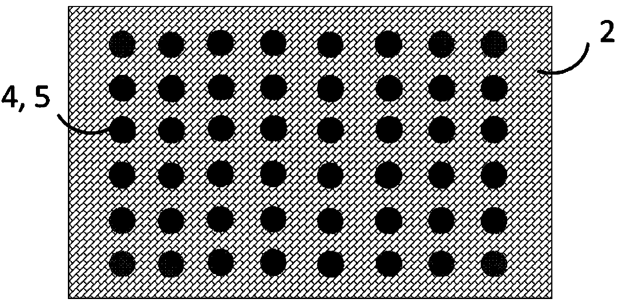
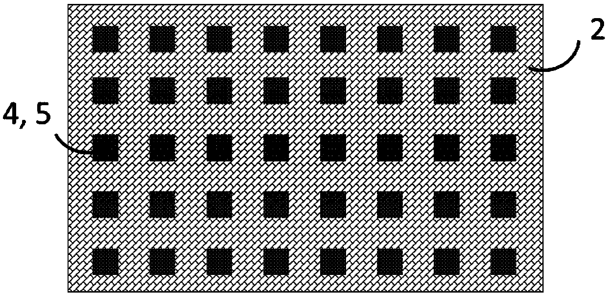
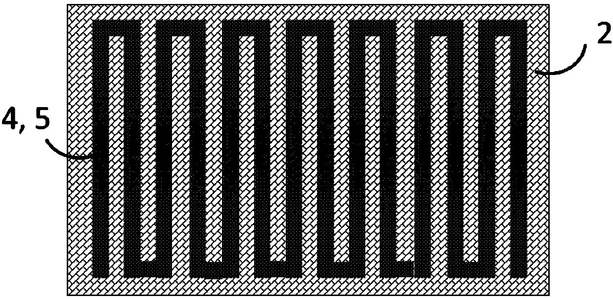
[0028] S1, using a separator as a substrate, printing electrode paste on the surface of the separator by printing technology or printing technology, so that the electrode paste is patterned and distributed on the surface of the separator.

[0029] S2, vacuum-drying the separator obtained in step S1 to solidify the electrode paste on the surface of the separator to form a patterned distribution of electrode materials.

[0030] S3, through vacuum coating technology or spray deposition technology, a layer of conductive film is plated or deposited on the entire surface of the patterned electrode material as a current collector, and then an integrated structure is obtained. The conductive thin layer obtained in this step evenly covers the electrode material to form a continuous conductive layer, there...

Embodiment 1

[0046] Select Celgard Model 2400 commercially available diaphragms (eg Figure 7 ), through the flat orifice printing process, the positive electrode paste of the battery is printed on one side of the separator. Among them, the thickness of the orifice plate is 30-500 μm, and the pattern of the orifice plate is distributed in a grid array; the positive electrode slurry is composed of lithium iron phosphate, conductive carbon black and PVDF in a ratio of 8:1:1. Subsequently, heat preservation at 80-150° C. for 2-24 hours, and solidify to obtain a separator substrate with grid-distributed electrode materials on the surface, and the size of the substrate is the size of A4 paper or equivalent. After curing, the diaphragm and the electrode material have a good bonding force, are not easy to fall off, and the diaphragm does not appear to be deformed.

[0047] Using the evaporation coating process, on the surface of the diaphragm base material on which the electrode material is prin...

Embodiment 2

[0055] Select the Celgard 2400 commercial separator, and print the battery negative electrode slurry on one side of the separator through the curved surface roll-to-roll perforated plate printing process. Among them, the thickness of the orifice plate is 30-500 μm, and the pattern of the orifice plate presents a crescent lock array distribution; the negative electrode slurry is composed of graphite, conductive carbon black and binder PVDF in a ratio of 8:1:1. Subsequently, heat preservation at 80-150°C for 2-24 hours, and solidify to obtain a separator base material with a dot matrix pattern (the overall pattern is circular) distributed on the surface electrode material; the base material is a rollable film with a width ≥ 10 cm and a length ≥ 100cm. After curing, the diaphragm and the electrode material have a good bonding force, are not easy to fall off, and the diaphragm does not appear to be deformed.

[0056] A direct current sputtering coating process is used to plate a ...


PUM

PropertyMeasurementUnit
thicknessaaaaaaaaaa
thicknessaaaaaaaaaa
thicknessaaaaaaaaaa

Abstract

The invention discloses a preparation method of a diaphragm, electrode and current collector integrated structure as well as a preparation method of a battery. The preparation method of the integratedstructure comprises the following steps of S1.taking a diaphragm as a matrix and printing electrode slurry on the surface of the diaphragm through a printing technology or a printing technology in order to distribute the electrode slurry on the surface of the diaphragm in a patterned mode; S2.carrying out vacuum drying on the diaphragm obtained in the step S1 in order to solidify the electrode slurry on the surface of the diaphragm to form an electrode material distributed in the patterned mode; and S3.plating or depositing a conductive thin film on the whole surface of the electrode materialdistributed in the patterned mode as a current collector through a vacuum coating technology or a spraying deposition technology in order to obtain the integrated structure. The integrated structureprepared by the invention is applied to the battery, so that the cycling performance of the battery can be improved, and the energy density of the battery can be improved.

Description

【Technical field】 [0001] The invention relates to the field of batteries, in particular to an integrated structure of a diaphragm, an electrode and a current collector, and a method for preparing the battery. 【Background technique】 [0002] The excessive consumption of traditional fossil energy has also caused huge disasters to the natural environment and the earth's ecosystem. It is particularly urgent to seek a green energy system that replaces traditional fossil energy and a green and energy-saving use mode of energy, and to seek harmony between man and the environment. In addition, with the advent of the information age, people's demand for fast, efficient, portable, and long-lasting electronic devices has increased rapidly. Electrochemical energy storage systems, especially the new generation of electrochemical energy storage systems represented by lithium-ion batteries, supercapacitors, lithium-sulfur batteries, lithium-air batteries, etc., have become the current Imp...

Claims


Application Information

Patent Timeline
Patent Type & Authority Applications(China)
IPC IPC(8): H01M2/14H01M2/18H01M50/403
CPCH01M50/403H01M50/463Y02E60/10
Inventor 杨诚邹培超吴铛
Owner SHENZHEN GRADUATE SCHOOL TSINGHUA UNIV
Why Eureka
Try Eureka