Eureka AIR delivers breakthrough ideas for toughest innovation challenges, trusted by R&D personnel around the world.

Calcium carbide production system and calcium carbide production method

A production system, calcium carbide technology, applied in the direction of carbide, calcium carbide, etc., can solve the problems of serious energy loss, large consumption of semi-coke, high cost, etc., and achieve the effects of less energy loss, high power utilization efficiency, and small dust pollution

Pending Publication Date: 2018-05-08
SHENWU TECH GRP CO LTD
View PDF0 Cites 1 Cited by
  • Summary
  • Abstract
  • Description
  • Claims
  • Application Information

AI Technical Summary

Problems solved by technology

The traditional calcium carbide furnace has a circular three-phase electrode structure, that is, the three electrodes are arranged inside the furnace body in a regular triangle shape, and the outer furnace body is circular. The disadvantage of this kind of calcium carbide furnace structure is that there are many arcs around the furnace that cannot function or have effective effects. Very poor places, that is, non-melting pool areas, make the temperature in these places not meet the reaction requirements, and the charge in this area cannot or is difficult to react. Due to the large difference in heat distribution, the effective utilization rate of electric energy is only 40-60 %, serious energy loss, resulting in low productivity of calcium carbide furnace, high power consumption, relatively large semi-coke consumption, and high cost

Method used


Image

  • Calcium carbide production system and calcium carbide production method
  • Calcium carbide production system and calcium carbide production method
  • Calcium carbide production system and calcium carbide production method

Examples


Embodiment

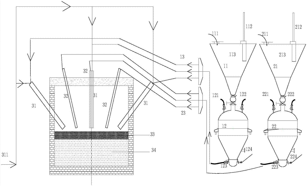
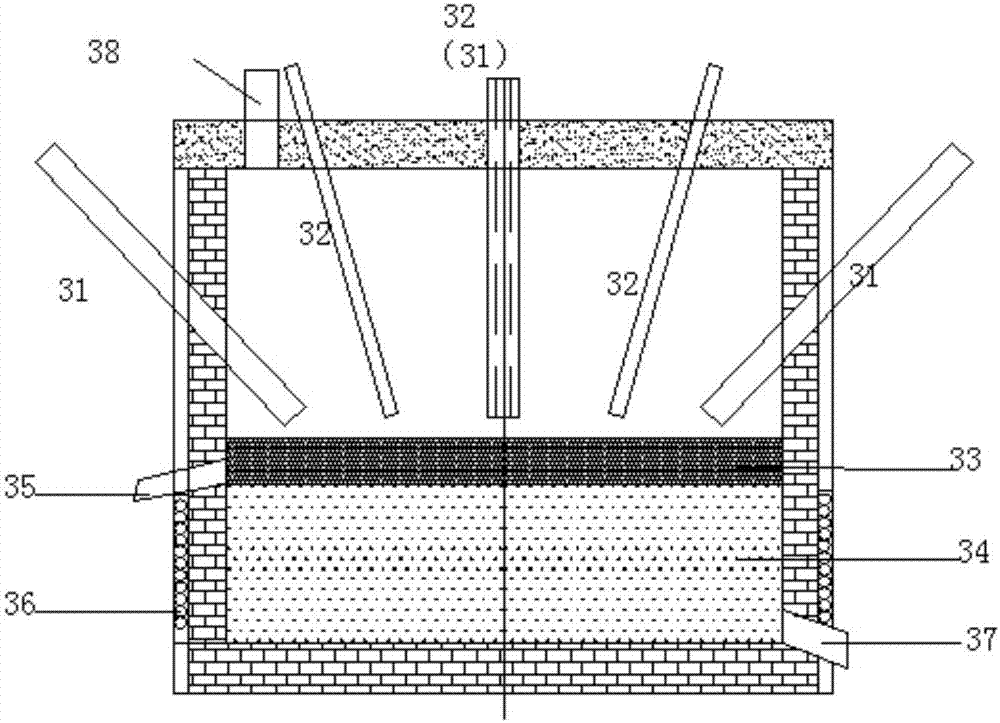
[0069] The furnace cover of the molten bath bed is unscrewed, scrap iron is added to the molten bath bed with a material tank, and the power supply device is started to heat the scrap iron by an induction coil to obtain molten iron. Add scrap iron to the furnace several times until the obtained molten iron level reaches the lowest point at the lower end of the liquid outlet, stop adding scrap iron, continue to send electricity to heat the molten iron, and when the temperature of the molten iron reaches 1800°C, properly reduce the power transmission to maintain the temperature of the molten iron at 1800°C.

[0070] Open the oxygen coal powder spray gun and lime powder spray gun, spray oxygen, coal powder and quicklime powder into the molten iron through the nozzles, wherein the mass ratio of C in the coal powder to CaO in the quicklime powder is: C:CaO=2.5:1 . Part of the injected coal powder reacts with oxygen to provide heat for the calcium carbide production reaction, and t...


PUM


Abstract

The invention relates to a calcium carbide production system and a calcium carbide production method. The system comprises a pulverized coal jetting subsystem, a pulverized lime jetting subsystem anda melting bath bed, wherein in the pulverized coal jetting subsystem, a pulverized coal jetting tank is provided with a pulverized coal inlet, a first compressed air inlet and a pulverized coal carrying air outlet; in the pulverized lime jetting subsystem, a pulverized lime jetting tank is provided with a pulverized lime inlet, a second compressed air inlet and a pulverized lime carrying air outlet; the furnace wall of the melting bath bed is provided with an aerobic pulverized coal spray gun and a pulverized lime spray gun, spray nozzles are positioned in a hearth, the furnace wall is provided with an induction coil connected with a power supply device, the aerobic pulverized coal spray gun is provided with an oxygen inlet and a pulverized coal inlet, and the pulverized lime spray gun isprovided with a pulverized lime inlet; and the pulverized coal inlet is connected with the pulverized coal carrying air outlet of the pulverized coal jetting tank through a pulverized coal distributor, and the pulverized lime inlet is connected with the pulverized lime carrying air outlet of the pulverized lime jetting tank through a pulverized lime distributor. The calcium carbide production system has the advantages of little dust pollution, no noise pollution, high electric energy utilization rate and low energy consumption.

Description

technical field [0001] The invention relates to the field of calcium carbide production, in particular to a calcium carbide production system and production method. Background technique [0002] The traditional process of producing calcium carbide by electrothermal method is to use the heat energy generated by the electric arc to make the carbon raw material and lime react at a temperature of 1800-2200 ℃ to produce calcium carbide. The main structure of the calcium carbide furnace includes the furnace body and electrodes. When the calcium carbide furnace is working, it is energized to generate an arc, and the high temperature generated by the arc is used to heat the charge to make the charge reach the heat required for the chemical reaction. Among them, the area where the high temperature emitted by the arc can directly act is called the arc working area or molten pool, which is located under the electrode tip to the bottom of the furnace. The traditional calcium carbide fu...

Claims


Application Information

Patent Timeline
Patent Type & Authority Applications(China)
IPC IPC(8): C01B32/942
Inventor 吴道洪喻善均温雨鑫丁力陈峨巩志坚远忠森
Owner SHENWU TECH GRP CO LTD
Why Eureka
Eureka Blog
Learn More