Ignition circuit for semiconductor spark plug of micro-pulsed plasma thruster

A pulsed plasma and spark plug technology, applied in the direction of using plasma, thrust reversers, machines/engines, etc., can solve the problems of power consumption and heat generation, large thermal stress, and increased spark plug temperature, so as to improve the utilization rate and reduce the Thermal stress, effect of reducing influence

Active Publication Date: 2018-05-08
NAT UNIV OF DEFENSE TECH
View PDF4 Cites 9 Cited by
  • Summary
  • Abstract
  • Description
  • Claims
  • Application Information

AI Technical Summary

Problems solved by technology

[0004] A separate ignition circuit is required, which increases the mass, volume and complexity of the system to a certain extent
[0005] There is a large thermal stress in the semiconductor spark plug, so that the life of the propulsion system is limited by the life of the spark plug
Continuous long-term discharge of semiconductor spark plugs in a vacuum will generate temperature accumulation, resulting in an increase in the temperature of the spark plugs. In addition, the large temperature difference between day and night in the space environment (up to 300 ° C), resulting in the widespread phenomenon of thermal expansion and contraction of spark plugs, resulting in large thermal stress. It may lead to partial discharge or non-standard discharge, which intensifies the ablation, corrosion and failure of the spark plug to a certain extent
[0006] The use of semiconductor spark plugs will affect the electrical efficiency of traditional ignition systems and the charging time of capacitors
When the ignition circuit is not working, the cathode and the center electrode of the traditional metal spark plug are completely isolated, and the circuit is equivalent to an open circuit; while the semiconductor spark plug will conduct the circuit, consume a certain amount of electric energy and generate heat (its own internal resistance Equivalent to a static equivalent resistance), at the same time, the static equivalent resistance is equivalent to parallel with the charging resistance, which will affect the charging time of the capacitor, thereby affecting the control accuracy

Method used


Image

  • Ignition circuit for semiconductor spark plug of micro-pulsed plasma thruster
  • Ignition circuit for semiconductor spark plug of micro-pulsed plasma thruster
  • Ignition circuit for semiconductor spark plug of micro-pulsed plasma thruster

Examples


Embodiment Construction

[0041] In order to make the object, technical solution and advantages of the present invention clearer, the present invention will be further described in detail below in conjunction with the accompanying drawings and specific implementation methods. It should be understood that the specific embodiments described here are only used to explain the present invention, and do not limit the protection scope of the present invention.

[0042] It should be noted that when an element is referred to as being “fixed on”, “disposed on” or “installed on” another element, it may be directly on the other element or there may be an intervening element. When an element is considered to be "connected" to another element, it may be directly connected to the other element or there may be an intervening element at the same time; the specific way that one element is fixedly connected to another element can be realized through existing technologies, and will not be discussed here. To repeat it agai...


PUM


Abstract

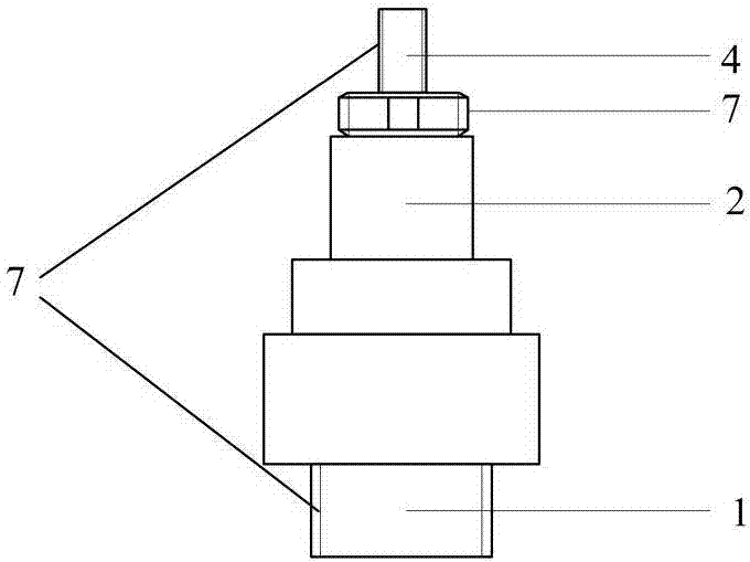
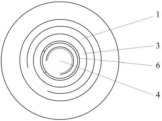
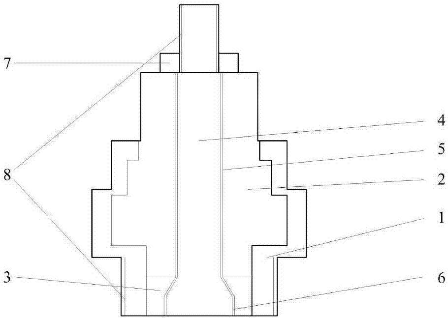
The invention provides an ignition circuit. The invention aims as solving the technical problems of optimizing the mass and volume of an ignition system, improving the electrical efficiency of the ignition system and the time control accuracy, reducing heat emission and heat stress of a semiconductor spark plug and the like, and the ignition circuit is designed for a micro-pulsed plasma thruster which is ignited through the semiconductor spark plug on the basis of not improving the complexity of an external circuit and not changing the basic configuration of the spark plug. Meanwhile, the installing and fixing manners of a central anode of the semiconductor spark plug are designed.

Description

technical field [0001] The invention relates to a semiconductor spark plug and its ignition system, which is especially suitable for inducing the main discharge of a micro-pulse plasma thruster to generate thrust. Background technique [0002] At present, the development of satellite system networking and miniaturization has put forward extensive demands on micro electric propulsion. Micro-Pulsed Plasma Thruster (μPPT) is a kind of Pulsed Plasma Thruster (PPT), which uses capacitor pulse discharge to generate electromagnetic field, working fluid ablation and ionization to generate plasma, and then accelerates through electromagnetic force plasma to generate thrust. Usually, a PPT with a system mass of less than 1kg is called μPPT, and the quality, volume and power consumption of μPPT are at least one order of magnitude lower than that of PPT. According to the physical state of the working fluid, μPPT can be divided into μPPT using gas working fluid, using liquid working fl...

Claims


Application Information

Patent Timeline
Patent Type & Authority Applications(China)
IPC IPC(8): F03H1/00
CPCF03H1/0087
Inventor 何兆福吴建军何振程玉强黄强张宇李健欧阳
Owner NAT UNIV OF DEFENSE TECH
Why Eureka
Try Eureka