Multi-functional four-rotation-wing aircraft of bionic hand

A four-rotor aircraft and multi-functional technology, applied in the field of aircraft, can solve the problems of limiting the use time of drones, affecting the flight of aircraft, and low accuracy, so as to improve work safety and reliability, improve shock absorption effect, and grasp Accurate effects on objects

Active Publication Date: 2018-05-18
ZHEJIANG OCEAN UNIV
View PDF6 Cites 6 Cited by
  • Summary
  • Abstract
  • Description
  • Claims
  • Application Information

AI Technical Summary

Problems solved by technology

[0003] Nowadays, drones have entered the homes of ordinary people, popularized in flight entertainment, aerial photography, etc., and drone products can be seen everywhere in the market. The drone market has opened up a new era in the current unmanned aircraft market. At present, drones are constantly Without entering human life, drones such as multi-rotors and aerial photography emerge in endlessly. Although traditional drones can fly in the sky, due to the high energy required for high-altitude flight, the endurance of traditional drones can only be in 20- 30 minutes greatly limits the use time of drones, and traditional drones

Method used


Image

  • Multi-functional four-rotation-wing aircraft of bionic hand
  • Multi-functional four-rotation-wing aircraft of bionic hand
  • Multi-functional four-rotation-wing aircraft of bionic hand

Examples


Embodiment 1

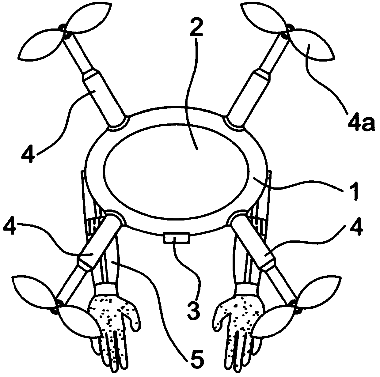
[0034] Such as figure 1 , 5 As shown, a bionic human-handed multifunctional quadrotor aircraft includes a flying frame 1, four rotors 4 are evenly connected around the flying frame 1, a solar panel 2 is connected to the inner side of the flying frame 1, and a miniature camera 3 is connected to the side of the flying frame 1 , the lower end of the flying frame 1 is connected with a manipulator 5 through a hydraulic spring shock absorber 6 . The flight frame 1 is the basic structural foundation of the aircraft, which can support aircraft components, stably connect them, and improve the anti-interference ability of the aircraft. The rotor 4 changes the rotation speed of the rotor 4 through the motor speed to realize the change of the lift force, thereby controlling the change of the attitude and position of the aircraft and ensuring the flexible operation of the aircraft. Retrieval of objects proceeds normally. The solar panel 2 utilizes solar semiconductor electronic devices ...

Embodiment 2

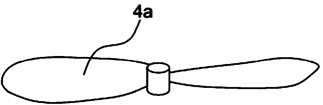
[0037] Such as Figure 1-9 As shown, on the basis of Embodiment 1, the present embodiment is further optimized as follows: the rotor 4 is connected to an independent motor, the head end of the rotor 4 is connected to the blade 4a, and the inclination angle of the blade 4a is preferably 6°. The four rotors 4 of the aircraft are respectively connected with the motors, and the adjacent motors control the blades 4a on the rotors 4 to rotate in reverse, so when the aircraft is in balanced flight, the gyro effect and the aerodynamic torque effect are all canceled out, and the blades 4a The setting of the inclination angle is conducive to forming a suitable pressure difference between the upper and lower sides of the blade 4a, so that the aircraft can achieve stable flight while having greater lift, which is the optimal inclination angle.

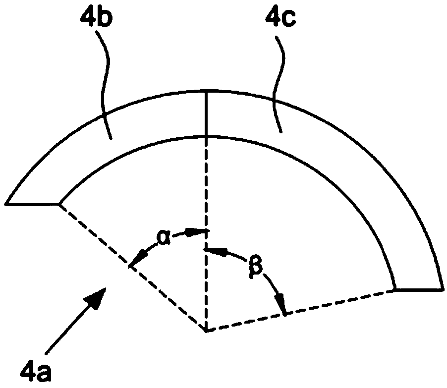
[0038] The paddle 4a is composed of an arc-shaped left paddle 4b and an arc-shaped right paddle 4c. The central angle α:β ratio of the left paddl...

Embodiment 3

[0047] Such as Figure 10 As shown, it is a flow chart of the action of the solar panel 2 on the aircraft of the present invention: the solar panel 2 uses a solar converter to generate a photoelectric effect, converts solar radiation energy into electrical energy, and supplies it to the motor of the aircraft, and the motor drives the aircraft wing to rotate, thereby realizing Long-term self-sufficiency power supply for quadrotor aircraft.

[0048] Such as Figure 11 As shown, among the four rotors 4 of the quadrotor aircraft of the present invention, the rotor F1 and the rotor F3 rotate clockwise, the rotor F2 and the rotor F4 rotate counterclockwise, the four rotors 4 are arranged in a cross, and the adjacent rotors rotate in the opposite direction , so that the quadrotor aircraft counteracts the gyroscopic effect of the aircraft, an underactuated system, is a vertical lift with six degrees of freedom, four input forces, and six state outputs.

[0049] Such as Figure 12 A...


PUM


Abstract

The invention discloses a multi-functional four-rotation-wing aircraft of the bionic hand, and belongs to the technical field of aircrafts. The aircraft includes a flying frame. The periphery of the flying frame is evenly connected with four rotation wings. The inner side of the flying frame is connected with a solar panel. The side surface of the flying frame is connected with a micro camera. Thelower end of the flying frame is connected with a mechanical arm through a hydraulic type spring shock absorber. The flying frame is a basic structural foundation of the aircraft. The flying frame can support the aircraft components, stabilize the connection, and improve the capacity of resisting disturbance of the aircraft. According to the multi-functional four-rotation-wing aircraft of the bionic hand, the modern solar photovoltaic power generation technology, the four-rotation-wing aircraft body structure, the mechanical arm, the spring shock absorbing system are used, existing defects ofan unmanned aerial vehicle are improved, using function that the unmanned aerial vehicle combines the mechanical arm is optimized, and the technical development of the unmanned aerial vehicle is propelled.

Description

technical field [0001] The invention belongs to the technical field of aircraft, and in particular relates to a bionic human-handed multifunctional quadrotor aircraft. Background technique [0002] UAVs first appeared in the 1920s. In 1914, the First World War was in full swing. The two generals of the United Kingdom, Carder and Pitcher, made a suggestion to the British Military Aeronautical Society: develop a drone that does not use drones. It is a small aircraft piloted by humans and controlled by radio, so that it can fly over a certain target area of ​​​​the enemy and drop the bombs loaded on the small aircraft in advance. This bold idea was immediately appreciated by Sir Day Henderson, then chairman of the British Military Aviation Society. He appointed Professor A.M. Luo to lead a group of people to develop it. The UAV was used as a target drone for training. is a term used by many countries to describe the latest generation of unmanned aircraft. Literally, the ter...

Claims


Application Information

Patent Timeline
IPC IPC(8): B64C27/08B64C11/20B64D1/22B64D27/24B25J15/00B25J9/00B25J19/00B25J19/02
CPCB64C11/20B64C27/08B64D1/22B64D27/24B25J9/0009B25J15/0009B25J19/0091B25J19/02B64U50/19B64U10/10B64U2101/00Y02T50/50
Inventor 苏玉香董小宇
Owner ZHEJIANG OCEAN UNIV
Why Eureka
Try Eureka