TM mode dielectric filter

A dielectric filter and dielectric resonator technology, which is applied to waveguide-type devices, resonators, electrical components, etc., can solve the problems of insufficient contact of resonators, decrease of TM mode dielectric quality factor, unstable electrical signal connection, etc. Achieve the effect of favorable heat dissipation, simple assembly, and excellent electrical performance

Inactive Publication Date: 2018-05-18
SICHUAN JIUDINGZHIYUAN INTPROP OPERATIONS CO LTD
View PDF4 Cites 4 Cited by
  • Summary
  • Abstract
  • Description
  • Claims
  • Application Information

AI Technical Summary

Problems solved by technology

[0004] The traditional installation method is to directly fix the TM mode dielectric resonator with metal screws. Screw fixing cannot ensure the full contact between the upper and lower surfaces of the resonator and the resonant cavity, and it is easy to cause damage to the resonator, result

Method used


Image

  • TM mode dielectric filter

Examples


Embodiment Construction

[0014] The following will clearly and completely describe the technical solutions in the embodiments of the present invention with reference to the accompanying drawings in the embodiments of the present invention. Obviously, the described embodiments are only some, not all, embodiments of the present invention. Based on the embodiments of the present invention, all other embodiments obtained by persons of ordinary skill in the art without making creative efforts belong to the protection scope of the present invention.

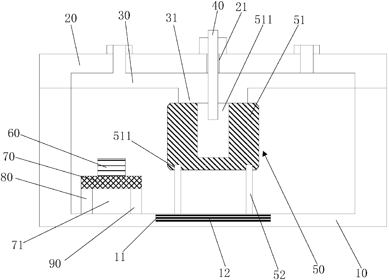
[0015] refer to figure 1 , is a schematic cross-sectional structure diagram of a TM mode dielectric filter provided by an embodiment of the present invention. The TM mode dielectric filter of the embodiment of the present invention includes a cavity 10 , a cover plate 20 , a cover plate flange 30 and a tuning screw 40 .

[0016] The cover plate 20 is covered on the cavity body 10, the cover plate flange 30 is screwed on the lower surface of the cover plate 20,...


PUM


Abstract

The invention discloses a TM mode dielectric filter. The dielectric cavity comprises a cavity, a cover plate, a cover plate flange and a tuning threaded rod; the cover plate covers the cavity; the cover plate flange is connected with the lower surface of the cover plate in a screw joint manner; a dielectric resonator, a microstrip line, a circuit board, a first supporting part and a second supporting part are arranged in the cavity; the two supporting parts are perpendicularly fixed at the bottom of the cavity; the circuit board is perpendicularly connected with the upper ends of the two supporting parts; the microstrip line is arranged on the circuit board; the dielectric resonator comprises dielectric resonance columns and supporting columns; a clamping groove is formed in the bottom surface of each dielectric resonance column; a tuning hole is formed in the top surfaces of the dielectric resonance columns in the axial direction; the top surfaces of the dielectric resonance columns are welded with the cover plate flange; a groove is formed in the bottom of the cavity; a conductive elastomer is arranged in the groove; the upper ends of the supporting columns are clamped in the clamping groove; the lower ends of the supporting columns prop against the conductive elastomer; a through hole which runs through up and down is formed in the cover plate; and the tuning threaded rod passes through the through hole of the cover plate and a hole of the cover plate flange to extend into the tuning hole downwardly. By virtue of the dielectric cavity, the quality factor can be improved.

Description

technical field [0001] The invention relates to the technical field of communication equipment, in particular to a TM mode dielectric filter. Background technique [0002] In communication equipment, the performance of the local oscillator has an important impact on the performance of signal reception. The local oscillator is usually generated by a specific frequency local oscillator chip or a dielectric filter. The structure of the local oscillator chip is simple, but it is expensive and requires an external reference clock frequency, so the application field is small. The dielectric filter is widely used in practice due to its advantages of small size, high quality factor, simple structure, and low cost. [0003] TM mode dielectric filter is an important means to realize miniaturization and light weight of radio frequency filter. According to the basic resonance principle of the TM mode dielectric resonator, the structure of this type of dielectric filter needs to meet ...

Claims


Application Information

Patent Timeline
IPC IPC(8): H01P1/20H01P7/10
CPCH01P1/2002H01P7/10
Inventor 罗艳
Owner SICHUAN JIUDINGZHIYUAN INTPROP OPERATIONS CO LTD
Why Eureka
Try Eureka