Device and technology for treating polycrystalline silicon byproduct slurry
A technology of polysilicon and slurry, applied in the direction of feeding device, halosilane, silicon compound, etc., can solve the problems of large investment, high energy consumption, high pollution, etc., achieve low energy consumption, reduce material loss, and be environmentally friendly
- Summary
- Abstract
- Description
- Claims
- Application Information
AI Technical Summary
Problems solved by technology
Method used
Image

Examples
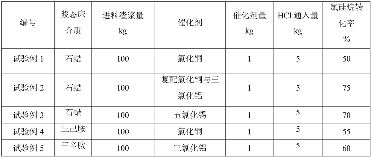
Embodiment 1
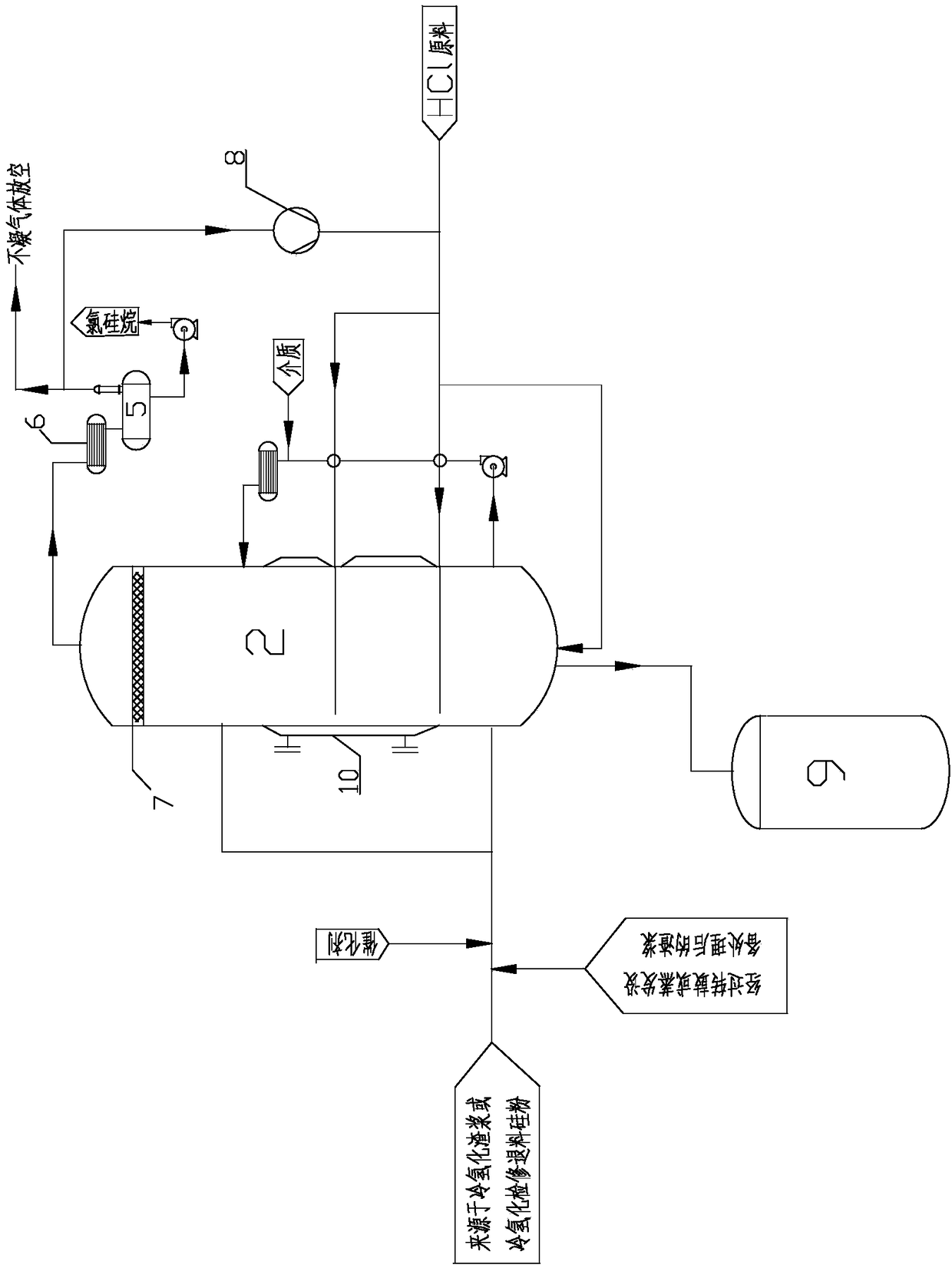
[0048] Such as figure 1 As shown, a device using a slurry bed to treat slurry in the production process of polycrystalline silicon includes a slurry bed reactor 2, and the outer wall of the slurry bed reactor 2 is provided with a slurry inlet and an HCl raw material inlet , the bottom of the slurry bed reactor 2 communicates with the waste tank 9 through a pipeline, and the top of the slurry bed reactor 2 communicates with the first storage tank 5 with the first heat exchanger through a pipeline, and the slurry bed A heat exchange device 10 is provided outside the reactor 2, and the heat exchange device is a jacket.
[0049] Wherein, the inside of the slurry bed reactor 2 is provided with a demister 7 near the top, which is used for treating the foam generated by the reaction materials in the slurry bed reactor.
[0050] Wherein, there are 2 described slurry feed inlets, 3 HCl raw material feed inlets, and one HCl raw material feed inlet is located at the bottom of the slurry...
Embodiment 2
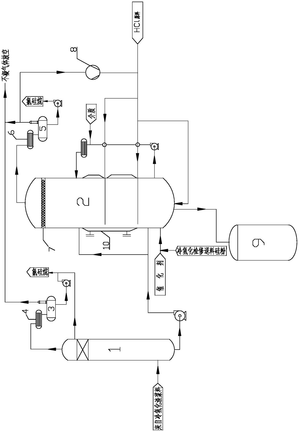
[0054] Such as figure 2 As shown, it is basically similar to the device in Example 1, the difference is that a heat exchange device 10 is provided outside the slurry bed reactor 2, the heat exchange device is a coil, and the slurry inlet is 3 There are 3 HCl raw material inlets, and two of the slurry inlets are communicated with the bottom of the flash tower 1 through pipelines, and the other slurry inlet is used to feed catalyst and / or cold hydrogenation Overhaul and return silicon powder. The top of the flash tower 1 is communicated with the second storage tank 3 with the third heat exchanger through a pipeline, and the top of the third heat exchanger is communicated with the outside atmosphere through a pipeline, and the chlorosilane liquid is collected through a pipeline above the flash tower 1, and flash A raw material feeding port is provided below the steaming tower 1 . As a preference, the second storage tank 3 with the third heat exchanger is preceded by the fourth...
Embodiment 3
[0056] use figure 1 or figure 2 The device shown is a process for processing the slurry in the polysilicon production process. The catalyst, the slurry in the polysilicon production process, and / or the silicon powder returned by cold hydrogenation maintenance are fed into the slurry inlet, and the HCl raw material is simultaneously fed into the HCl The raw material feed port controls the temperature of the slurry bed reactor by circulating condensing medium into the jacket, and the chlorosilane gas obtained by the reaction enters the first storage tank with the first heat exchanger through the top pipe of the slurry bed reactor. The tank is condensed into liquid silane and collected, and the non-condensable gas is emptied through the pipeline, and the waste after reaction is deposited at the bottom of the slurry bed reactor, and is regularly discharged to the waste tank.
[0057] Wherein, the catalyst is one or more of cupric chloride, cuprous chloride, aluminum chloride and...
PUM
 Abstract
Description
Claims
Application Information