Method for producing ethylene cracking material through liquefied gas hydrogenation

A technology for ethylene cracking and liquefied gas, which is applied in the processing of gas mixtures, hydrocarbon oil treatment products, petroleum industry, etc. It can solve the problems of high olefin content, fast carbon deposition in the catalyst bed, and difficulty in achieving the quality of raw materials for steam cracking. Achieve the effect of realizing the conversion rate and controlling the reaction speed

Active Publication Date: 2018-05-29
CHINA PETROLEUM & CHEM CORP +1
View PDF6 Cites 3 Cited by
  • Summary
  • Abstract
  • Description
  • Claims
  • Application Information

AI Technical Summary

Problems solved by technology

This method solves the C 4 The stability of the distillate hydrogenation process solves the problem that the olefin content in the hydrocoked gasoline obtained from the coker gasoline hydrogenation unit is high, and it is difficult to meet the quality requirements of steam cracking raw materials
However, in actual industrial installat

Method used


Image

  • Method for producing ethylene cracking material through liquefied gas hydrogenation
  • Method for producing ethylene cracking material through liquefied gas hydrogenation
  • Method for producing ethylene cracking material through liquefied gas hydrogenation

Examples


Embodiment 1

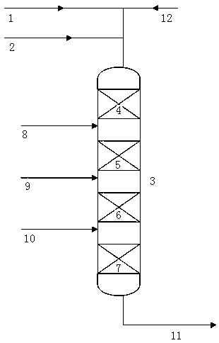
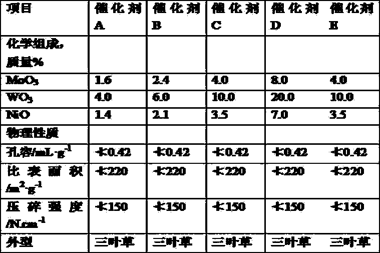
[0050] The reaction adopts a fixed-bed reactor with upper feed mode. The catalyst is packed in four stages, along the direction of material flow, in equal volume proportions. From top to bottom, the catalysts are A, B, C, D in sequence. The reaction process does not adopt a stepwise hydrogen feed scheme. The raw materials of hydrogen and liquefied gas enter the reactor from the inlet of the first reaction section. The physical properties of the catalyst used in the reaction are shown in Table 2. The catalyst needs to be vulcanized when in use, and the vulcanization operation is carried out by conventional vulcanization methods in this field, and will not be repeated. The reaction conditions and results are shown in Table 4. Table 5 shows the amount of coke deposited in each section of the catalyst bed after operation.

Embodiment 2

[0052] The reaction adopts a fixed-bed reactor with upper feed; the catalyst adopts four-stage packing, and is packed in equal volume ratio along the direction of material flow. From top to bottom, the catalysts are A, B, C, D in sequence. The reaction is divided into four stages to enter hydrogen, the amount of hydrogen entering the bed in each stage is: the amount of hydrogen entering the first catalyst bed in the first stage is 30v% of the chemical hydrogen consumption required for the reaction, and the second stage enters the second catalyst The amount of hydrogen in the bed is 30v% of the chemical hydrogen consumption required for the reaction, the amount of hydrogen entering the third catalyst bed in the third stage is 30v% of the chemical hydrogen consumption required for the reaction, and the fourth stage enters the fourth catalyst bed The amount of hydrogen is 50v% of the chemical hydrogen consumption required for the reaction. The physical properties of the catalyst ...


PUM


Abstract

The invention discloses a method for producing an ethylene cracking material through liquefied gas hydrogenation. The method is characterized in that liquefied gas and hydrogen pass through a hydrogenation reactor through a cocurrent flowing mode, then are contacted with a hydrogenation catalyst under hydrogenation technical condition and subjected to a reaction; the hydrogenation reactor comprises more than two reaction segments, and according to a contact sequence with a reaction material, the activity of the catalyst in a downstream reaction segment is higher than the activity of the catalyst in an upstream reaction segment. The method reduces the relative average reaction speed at an entrance of a catalyst bed layer, changes problem of large relative average reaction speed at the entrance of the catalyst bed layer, a difference of the average reaction speed of each segment of the catalyst bed layer is greatly reduced, and the relative average reaction speed of each segment of the catalyst bed layer is more uniform.

Description

Technical field [0001] The invention relates to a method for hydrogenating liquefied petroleum gas to produce ethylene cracking feed, in particular to a method for hydrogenating liquefied petroleum gas using a catalyst graded filling method. Background technique [0002] With the development of the oil refining industry, especially the continuous improvement of catalytic cracking technology, the deep processing of refinery gas has attracted more and more attention. There are many ways to utilize refinery gas, among which the hydrogenation of liquefied gas is one of the topics of common concern. After hydrogenation of liquefied gas, there will be many uses, such as ethylene raw material, raw material for synthetic maleic anhydride, and liquefied petroleum gas for vehicles. Among them, liquefied gas is used as raw material for ethylene due to its large amount and many production equipment. Be concerned. [0003] As far as ethylene raw materials are concerned, although the compositi...

Claims


Application Information

Patent Timeline
IPC IPC(8): C10G70/02
CPCC10G70/02C10G2400/20
Inventor 徐彤艾抚宾乔凯祁文博袁毅
Owner CHINA PETROLEUM & CHEM CORP
Why Eureka
Try Eureka