Colorful transparent conductive thin film as well as preparation method and application thereof
A technology of transparent conductive film and color, which is applied in the direction of equipment for manufacturing conductive/semiconductive layers, cable/conductor manufacturing, conductive layers on insulating carriers, etc., to achieve improved weather resistance, multi-color selection, and reduced types. effect
- Summary
- Abstract
- Description
- Claims
- Application Information
AI Technical Summary
Problems solved by technology
Method used
Image


Examples
preparation example Construction
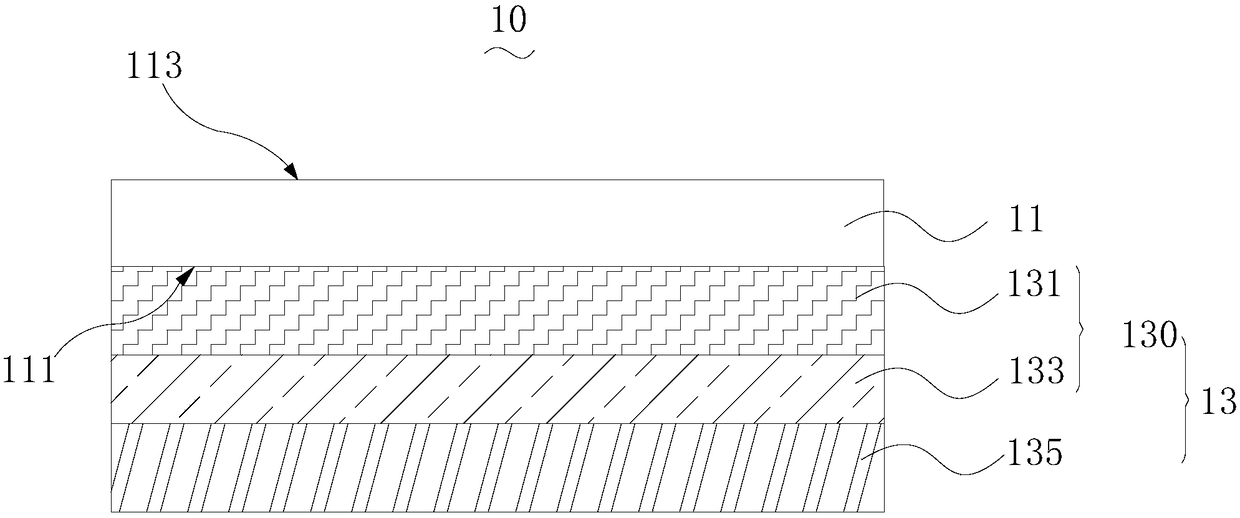
[0045] The preparation method of above-mentioned colored transparent conductive film 10 comprises:
[0046] S110 , preparing an interference layer 130 on the surface of the transparent substrate 11 .
[0047] In one embodiment, the interference layer 130 is prepared on the transparent substrate 11 by magnetron sputtering. The interference layer 130 is preferably prepared by off-line PVD magnetron sputtering.
[0048] In one embodiment, the interference layer 130 is prepared by magnetron sputtering, wherein argon or an argon-oxygen mixed gas is introduced into the magnetron sputtering process. Preferably, the flow rate ratio of argon to oxygen is 100:1˜1:1:. The target-base distance is 3 cm to 15 cm, preferably 5 cm to 10 cm.
[0049] In one of the embodiments, the high refractive index layer is prepared by off-line PVD magnetron sputtering, the high refractive index layer is sputtered by direct current, the sputtering power is 2kW-30kW, preferably 5kW-20kW; the heating temp...
Embodiment 1
[0060] The high refractive index layer and the low refractive index layer of the interference layer are sequentially deposited on a 3.20mm ultra-clear transparent glass substrate. Among them, the high refractive index layer is deposited by direct current sputtering of ITO planar target, and the sputtering conditions are: argon 1000 sccm, oxygen 30 sccm, sputtering power 5 kW, target base distance 6.0 cm, ultra-white transparent glass substrate temperature 300 ℃; The refractive index layer is made of a Si rotating target, and deposited by sputtering with a 40 kHz AC power source. The sputtering conditions are: argon gas 600 sccm, oxygen gas 400 sccm, sputtering power 10 kW, target base distance 6.0 cm. Then, a conductive layer was deposited on the low refractive index layer by direct current sputtering of an ITO planar target. The sputtering conditions were: argon 1000 sccm, oxygen 30 sccm, sputtering power 5 kW, target base distance 6.0 cm, ultra-white transparent glass substra...
Embodiment 2
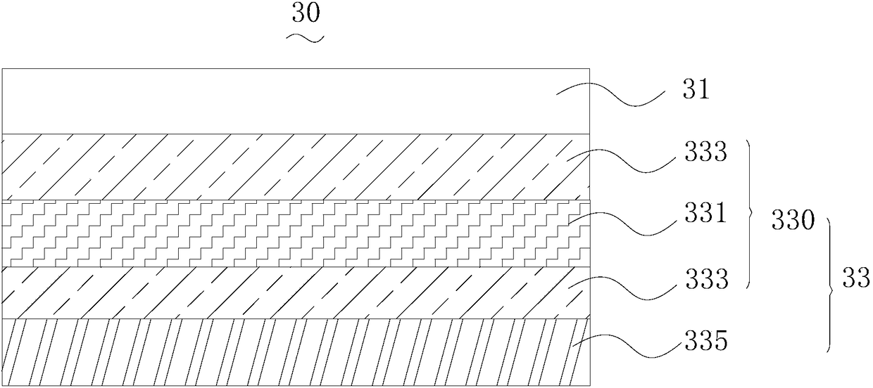
[0063] The low-refractive-index layer and the high-refractive-index layer of the interference layer were deposited on a 3.20 mm ultra-clear transparent glass substrate. Among them, the low refractive index layer is deposited by sputtering with Si rotating target and 40kHz AC power supply. The sputtering conditions are: argon gas 600sccm, oxygen 400sccm, sputtering power 10kW, target base distance 6.0cm. On the low-refractive-index layer, a high-refractive-index layer was deposited by direct current sputtering of an ITO planar target. The sputtering conditions are: argon gas 1000 sccm, oxygen gas 30 sccm, sputtering power 5 kW, target base distance 6.0 cm, ultra-white transparent glass substrate temperature 300°C. Then, on the low refractive index layer of the interference layer, use the ITO planar target to deposit the conductive layer by DC sputtering. The sputtering conditions are: argon 1000sccm, oxygen 30sccm, sputtering power 5kW, target base distance 6.0cm, ultra-white a...
PUM
| Property | Measurement | Unit |
|---|---|---|
| Thickness | aaaaa | aaaaa |
| Square resistance | aaaaa | aaaaa |
| Resistivity | aaaaa | aaaaa |
Abstract
Description
Claims
Application Information