
Metal powder preparation device and preparation method

A technology for preparing device and metal powder, applied in the field of powder metallurgy, can solve the problems of wide powder particle size distribution, large average particle size of powder, affecting powder quality, etc., and achieve the effect of narrow particle size distribution, stable product quality and low product cost

Inactive Publication Date: 2018-06-05
BEIJING COMPO ADVANCED TECH
View PDF7 Cites 20 Cited by
  • Summary
  • Abstract
  • Description
  • Claims
  • Application Information

AI Technical Summary

Problems solved by technology

The gas atomization method is one of the important methods for the preparation and large-scale production of rapidly solidified metal powders. However, the existing gas atomization methods have problems such as wide powder particle size distribution, low powder extraction rate, high energy consumption, and easy furnace blockage.
In U.S. Patent No. 5,242,508, a typical method for preparing metal powder is proposed, that is, a close-coupled gas atomization powder making method. This invention provides an alloy powder that can produce a higher melting point, but the average particle size of the powder is large. The powder particle size distribution is wide, the powder extraction rate is low, and the furnace is easy to block, etc.; the method and device proposed by the Chinese patent CN104550987A have similar problems. These problems are important factors that affect the quality of the powder and increase the cost of the powder. solve

Method used

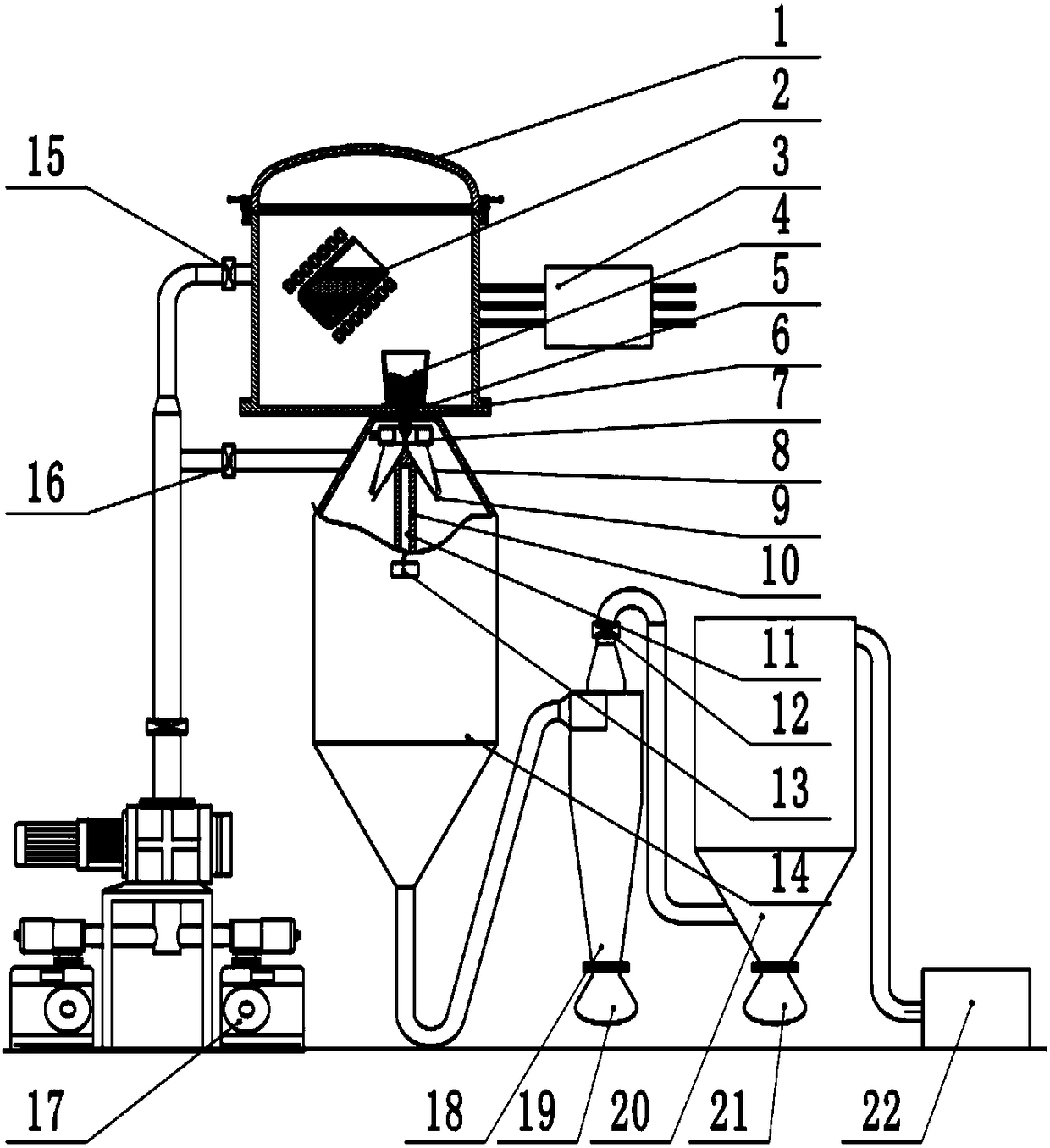

Image

  • Metal powder preparation device and preparation method
  • Metal powder preparation device and preparation method
  • Metal powder preparation device and preparation method

Examples


Embodiment 1

[0052] Example 1 Production of 316L stainless steel powder for 3D printing

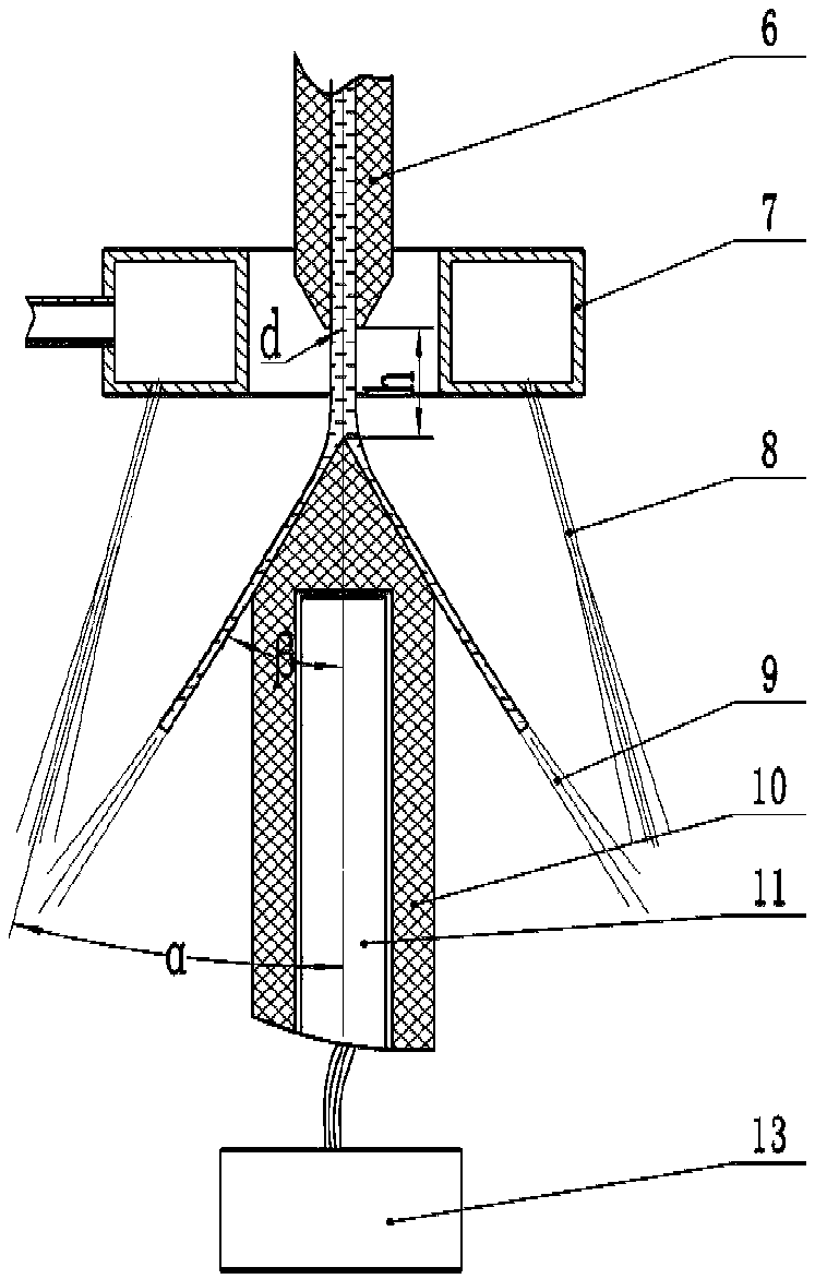
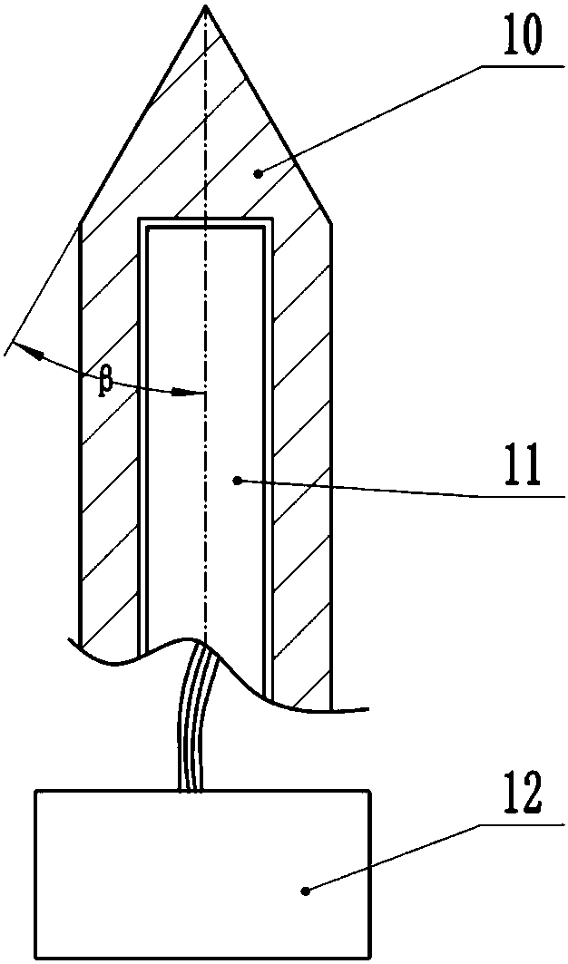
[0053] In the equipment used in this embodiment, the gas atomizing nozzle 7 is an annular nozzle, and the angle α between the center line of the spraying nozzle and the center line of the gas atomizing nozzle 7 is 35°. The diameter d at the outlet of the inner hole of the nozzle 6 is 5 mm. The distance h between the top of the melt disperser 10 and the bottom surface of the nozzle 6 is 30 mm; the top surface of the melt disperser 10 is conical, and the angle β between the generatrix of the cone surface and the center line of the cone surface is 45°. The portion of the melt disperser 10 that is in contact with the melt, that is, the tapered portion, is made of boron nitride.

[0054] The specific production of 316L stainless steel powder includes the following steps:

[0055] S1: Furnace loading, put 80KG metal into the smelting ladle 2 according to the designed ratio;

[0056] S2: prepare the atmos...

Embodiment 2

[0060] Embodiment 2 Production of copper-phosphorus welding powder for brazing

[0061] In the equipment used in this embodiment, the gas atomizing nozzle 7 is an annular nozzle with 20 nozzle holes, and the angle α between the centerline of the nozzle hole and the centerline of the gas atomizing nozzle 7 is 30°. The diameter d at the outlet of the inner hole of the nozzle 6 is 6 mm. The distance h between the top of the melt disperser 10 and the bottom surface of the nozzle 6 is 46 mm; the top surface of the melt disperser 10 is conical, and the angle β between the generatrix of the cone surface and the center line of the cone surface is 55°. The portion of the melt disperser 10 that is in contact with the melt, that is, the tapered portion, is made of alumina.

[0062] The specific production of copper phosphorous welding powder includes the following steps:

[0063] S1: Furnace loading, put 90KG metal into the smelting ladle 2 according to the designed ratio;

[0064] S2...

Embodiment 3

[0068] Example 3 Production of tin powder

[0069] In the equipment used in this embodiment, the gas atomizing nozzle 7 is an annular nozzle with 10 nozzle holes, and the angle α between the centerline of the nozzle hole and the centerline of the gas atomizing nozzle 7 is 45°; The diameter d at the outlet of the inner hole is 2mm. The distance h between the top of the melt disperser 10 and the bottom surface of the flow nozzle 6 is 60mm; the top surface of the melt disperser 10 is a concave curved surface conical shape, and the bottom of the conical surface is in the shape of a tangent along the direction of the generatrix and the center line of the conical surface. The angle β is 80°; the part of the melt disperser 10 in contact with the melt, that is, the conical part, is made of titanium.

[0070] The method for preparing metal powder by using the device for preparing metal powder comprises the following steps:

[0071] S1: Furnace loading, put 85KG metal into the smeltin...


PUM


Abstract

The invention relates to a metal powder preparation device and method. The device consists of a control system, a smelting system, a vacuum system, an atomizing chamber, a pressure control system, a dust removing system and other parts. An atomizer in the atomizing chamber includes an atomizing nozzle, a flow nozzle and a melting body disperser; the atomizing nozzle and the flow nozzle are positioned above the melting body disperser, the central line of the atomizing nozzle is superposed with the central line of the melting body disperser and the central line of the flow nozzle, and the flow nozzle is installed at the bottom of a smelting chamber and stretches into the atomizing chamber. The method includes the steps that metal is fed into a furnace, heating and smelting are carried out onthe metal, melted bodies are ejected into the melting body disperser in the atomizing chamber under the action of the gravity and gas pressure and dispersed into liquid drops, the liquid drops are atomized into finer liquid drops, and then the finer liquid drops are cooled and solidified into metal powder. The metal powder preparation method has the advantages that the controllability of powder size is great, the powder size distribution is narrow, the furnace is not likely to be blocked, energy is saved, and the environment is protected.

Description

technical field [0001] The invention relates to the technical field of powder metallurgy, in particular to a device and method for preparing metal powder by an atomization method. Background technique [0002] Metal powders are used in almost all industrial fields. Among them, because of their excellent physical, chemical, and mechanical properties, rapidly solidified metal powders have gained great popularity in many fields such as machinery, electronics, chemical industry, military industry, and aerospace. important and widely used. The gas atomization method is one of the important methods for the preparation and large-scale production of rapidly solidified metal powders. However, the existing gas atomization methods have problems such as wide powder particle size distribution, low powder extraction rate, high energy consumption, and easy furnace blockage. In U.S. Patent No. 5,242,508, a typical method for preparing metal powder is proposed, that is, a close-coupled gas ...

Claims


Application Information

Patent Timeline
Patent Type & Authority Applications(China)
IPC IPC(8): B22F9/08
CPCB22F9/082B22F2009/0888
Inventor 张少明贺会军朱学新刘建林刚赵新明刘英杰张金辉边隽杰袁国良王志刚安宁祝志华
Owner BEIJING COMPO ADVANCED TECH
Learn More