Vacuum plating cathode target using foam metal for enhancing cooling effect

A metal foam and cathode target technology, which is applied in the field of vacuum plating cathode target, can solve the problems of low heat transfer efficiency between the target material and the back plate, limited increased area, and reduced heat transfer efficiency, so as to improve uneven heating, Effect of preventing local overheating and improving cooling efficiency

Pending Publication Date: 2018-06-08
WUZHOU HGP ADVANCED MATERIALS TECH CORP
View PDF11 Cites 1 Cited by
  • Summary
  • Abstract
  • Description
  • Claims
  • Application Information

AI Technical Summary

Problems solved by technology

[0009] At present, most cathode targets use this indirect cooling method, but there is a problem with this cooling method: the heat transfer efficiency between the target and the back plate is not high, because the surface of the target and the back plate are not Ideal for smooth surfaces (such as image 3 shown), and the contact between the two surfaces is achieved by mechanical compression, so microscopically, there will be many gaps at the contact surface, and the gaps are filled with air, which reduces the efficiency of heat transfer
[0010] In general, whether direct cooling or indirect cooling is used, there is the same problem: the heat exchange between the cooling liquid and the target, and between the cooling liquid and the back plate can only be through the point where they are in direct contact. The interface conducts heat exchange, in other words the width of the coolant channel determines the rate of heat exchange
As the new process requires more and more sputtering power, the calorific value of the target will also increase, and the old cooling method is difficult to meet the future process requirements
Patent No. CN202054888 U's "A Magnetron Sputtering Device" can increase the contact area with the cooling medium and improve the cooling effect "Although this method increases the heat exchange area to a certain extent, the increased area is limited and the effect is also limited.

Method used


Image

  • Vacuum plating cathode target using foam metal for enhancing cooling effect
  • Vacuum plating cathode target using foam metal for enhancing cooling effect
  • Vacuum plating cathode target using foam metal for enhancing cooling effect

Examples


Embodiment 1

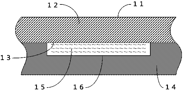
[0032] This embodiment shows a vacuum plating cathode target that uses metal foam to enhance cooling, such as Figure 4 As shown, it includes a yoke 41, a magnet 42, a target 45, a back plate 43, a graphite sheet 44, a copper foam 47, and a coolant flow channel 46, wherein the back plate 43 is made of a copper plate with a thickness of 0.1 mm. A graphite sheet 44 with a thickness of 0.02 mm is arranged between the target 45 and the back plate 43, and a copper foam 47 with an average hole diameter of 0.1 mm is welded on the other side of the back plate 43, and the copper foam 47 is processed to be compatible with the cooling liquid After the size of the flow channel 46 matches, it is filled inside the coolant flow channel 46 . The back plate 43 and the copper foam 47 are connected together by high frequency welding. When the cathode target is working, the coolant flows through the coolant flow channel filled with copper foam, and uses the large surface area of ​​the foam coppe...

Embodiment 2

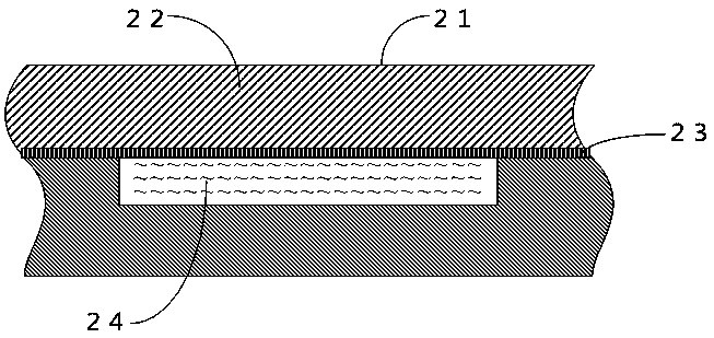
[0034] This embodiment shows a vacuum plating cathode target that uses metal foam to enhance cooling, such as Figure 5 As shown, it includes a yoke 51, a magnet 52, a target 56, a back plate 54, a separator 53, a graphite sheet 55, an aluminum foam 58, and a cooling liquid flow channel 57, wherein the back plate 54 is made of a copper plate with a thickness of 1 mm. A layer of graphite sheet 55 with a thickness of 0.1 mm is arranged between the target material 56 and the back plate 54 . A copper-plated aluminum foam 58 is welded on the other side of the back plate 54, and its average hole diameter is 2 mm. The aluminum foam 58 is processed into a size matching the cooling liquid flow channel 57 and then filled inside the cooling liquid flow channel 57 . The back plate 54 and the aluminum foam 58 are connected together by brazing, and the solder used for brazing is Sn—Bi alloy solder with a melting point of 160° C. When the cathode target is working, the coolant flows throug...


PUM

PropertyMeasurementUnit
thicknessaaaaaaaaaa
diameteraaaaaaaaaa
porosityaaaaaaaaaa

Abstract

The invention relates to a vacuum plating cathode target using foam metal for enhancing a cooling effect. The vacuum plating cathode target comprises a magnet yoke, a magnetic body, a target material,a backboard, a graphite flake, the foam metal and a cooling liquid flow channel. The graphite flake arranged between the target material and the backboard is used for decreasing the thermal contact resistance, the foam metal which is tightly connected to the other surface of the backboard and is further filled into the cooling liquid flow channel is used for increasing the heat exchange area, andthe cooling effect is enhanced.

Description

technical field [0001] The invention relates to a vacuum plating cathode target, in particular to a vacuum plating cathode target which uses foam metal to enhance cooling. Background technique [0002] In the vacuum coating production process, in order to improve production efficiency and film quality, people often obtain higher sputtering rates by increasing the flow of ions per unit time, and by applying a higher target voltage to make the ion hit the target surface. The higher velocity results in higher energies for the atoms escaping the target surface. This is achieved by increasing the power of the target. During the production process, the target is continuously bombarded by charged particles, and most of the energy is converted into heat, which causes the target itself to heat up. The temperature of the target rises sharply, which will damage the non-high temperature resistant. For the target material, there will be more large particles among the particles emitted a...

Claims


Application Information

Patent Timeline
Patent Type & Authority Applications(China)
IPC IPC(8): C23C14/34
CPCC23C14/3407
Inventor 穆俊江韦雁途吴天和
Owner WUZHOU HGP ADVANCED MATERIALS TECH CORP
Why Eureka
Try Eureka