Silicon material cleaning method

A technology for silicon materials and cleaning tanks, applied in cleaning methods using tools, cleaning methods using liquids, cleaning methods and utensils, etc., can solve the problems of large silicon material loss, improve quality, reduce costs, and reduce loss rates Effect

Active Publication Date: 2018-06-29
广德盛源电器有限公司
View PDF14 Cites 2 Cited by
  • Summary
  • Abstract
  • Description
  • Claims
  • Application Information

AI Technical Summary

Problems solved by technology

[0010] Silicon material is first oxidized by nitric acid and then reacted with hydrofluoric acid in the cleaning process. The silicon material is corroded by acid to remove a layer of surface layer to achieve the cleaning effect. After cleaning, the loss of silicon material is relatively large.

Method used


Image

  • Silicon material cleaning method
  • Silicon material cleaning method

Examples


Embodiment 1

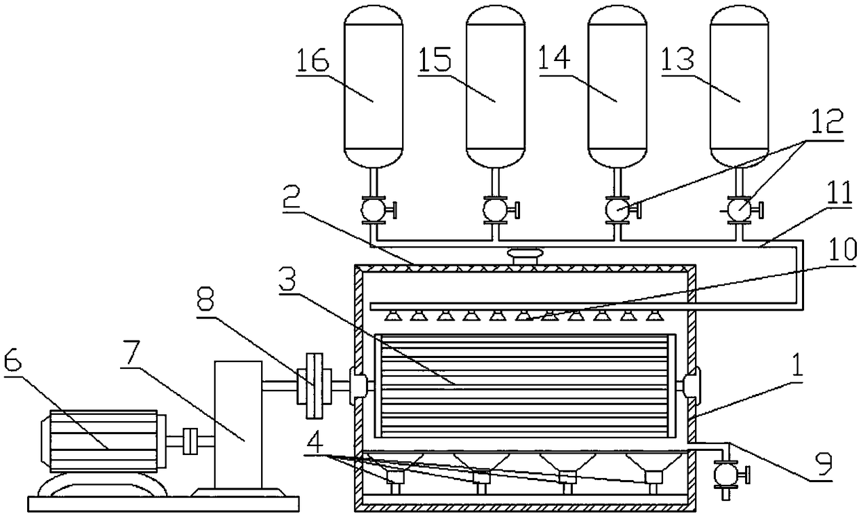
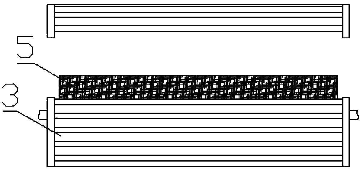
[0034] see Figure 1-2 As shown, the technical solution adopted in the present invention is: a cleaning method for silicon materials, the main structure of the silicon material cleaning device is designed as a cleaning tank 1, a cleaning drum 3 is installed in the cleaning tank 1, and the cleaning drum 3, a cleaning brush 5 is installed inside, and the cleaning drum 3 is powered by a driving motor 6, a speed regulating device 7 is installed on the right side of the driving motor 6, and an ultrasonic generator 4 is installed at the bottom of the cleaning tank 1, so that The middle and lower part of the right side of the cleaning tank 1 is provided with a water outlet pipe 9, and the top of the right side of the cleaning tank 1 is provided with a water inlet pipe 11, and the water inlet pipe 11 is installed with a spray device 10 on a section inside the cleaning tank 1, The head of described water inlet pipe 11 is connected with pure water tank 15, ethanol aqueous solution tank ...

Embodiment 2

[0050] The difference between this embodiment and embodiment 1 is:

[0051] The concentration of the aqueous ethanol solution contained in the aqueous ethanol tank 13 is 8%.

[0052] The lye contained in the lye tank 14 is a dilute mixed solution of sodium hydroxide and sodium carbonate, wherein the concentration of the dilute mixed solution of sodium hydroxide and sodium carbonate is designed to be 6%.

[0053] The acid liquid inside the acid liquid tank 16 is a dilute mixed solution of hydrofluoric acid, nitric acid and hydrochloric acid, wherein the concentration of the dilute mixed solution of hydrofluoric acid, nitric acid and hydrochloric acid is designed to be 5%.

[0054] In step 1 of the silicon material cleaning method, the frequency of the ultrasonic transmitter 4 is set to 35 MHz, and in step 4, the frequency of the ultrasonic transmitter 4 is set to 20 MHz.

[0055] In step 6 of the silicon material cleaning method, the baking temperature in the oven is set to 12...

Embodiment 3

[0057] The difference between this embodiment and embodiment 1 is:

[0058] The concentration of the aqueous ethanol solution contained in the aqueous ethanol tank 13 is 10%.

[0059] The lye contained in the lye tank 14 is a dilute mixed solution of sodium hydroxide and sodium carbonate, wherein the concentration of the dilute mixed solution of sodium hydroxide and sodium carbonate is designed to be 10%.

[0060] The acid liquid inside the acid liquid tank 16 is a dilute mixed solution of hydrofluoric acid, nitric acid and hydrochloric acid, wherein the concentration of the dilute mixed solution of hydrofluoric acid, nitric acid and hydrochloric acid is designed to be 6%.

[0061] In step 1 of the silicon material cleaning method, the frequency of the ultrasonic transmitter 4 is set to 38 MHz, and in step 4, the frequency of the ultrasonic transmitter 4 is set to 25 MHz.

[0062] In step 6 of the silicon material cleaning method, the baking temperature in the oven is set to ...


PUM


Abstract

The invention discloses a silicon material cleaning method. A body structure of a silicon material cleaning device is designed into a cleaning tank. A cleaning tank cover is placed on the top of the cleaning tank. A cleaning roller is arranged in the cleaning tank and internally provided with a cleaning brush. Power is provided for the cleaning roller through a drive motor. A speed adjusting device is arranged on the right side of the drive motor. A connecting bearing is arranged between the speed adjusting device and the cleaning tank. An ultrasonic generator is arranged at the bottom of thecleaning tank. The cleaning method comprises the steps that a silicon material is subjected to ultrasonic ethanol-water flushing and then is immersed through dilute alkali liquid, then, spraying is conducted through dilute acid liquid, finally, high-pressure washing is conducted, and then drying is conducted after water spinning-dry. By means of the silicon material cleaning method, impurities onthe surface of the silicon material can be effectively cleaned away, the reaction is stable, heat is basically not generated, and the oxidization reaction is not generated; and pollution to the silicon material due to oxidization is avoided, and the silicon material quality is improved; and the silicon material loss rate is reduced, and cost is saved.

Description

technical field [0001] The invention relates to the technical field of cleaning materials for electronic and electrical parts, in particular to a method for cleaning silicon materials. Background technique [0002] China's photovoltaic industry has entered a new stage of rapid development. The industrial chains of raw silicon, silicon wafers, cells, modules, etc. seem to be independent of each other but are closely linked. The output of primary silicon determines the healthy and stable development of downstream industries. How to make more and better use of other silicon raw materials is also a technical problem for silicon wafer manufacturers. [0003] In the photovoltaic industry, each process will produce excess silicon material waste, such as scrap material, which is the excess monocrystalline silicon material surrounding the usable part during the cutting process of the single crystal rod, and its quality is equivalent to that of finished silicon wafers; , that is, in ...

Claims


Application Information

Patent Timeline
Patent Type & Authority Applications(China)
IPC IPC(8): B08B1/00B08B1/02B08B3/02B08B3/08B08B3/12B08B7/04F26B5/08
CPCF26B5/08B08B3/022B08B3/08B08B3/123B08B7/04B08B1/20B08B1/12
Inventor 盛广喜
Owner 广德盛源电器有限公司
Why Eureka
Try Eureka