
Crawling robot and marine steel surface pretreatment process

A technology for crawling robots and ships, applied in the field of laser processing, can solve the problems of low cleaning efficiency, low production capacity, and high metal loss, and achieve the effects of stable and reliable quality, overcoming the effect of gravity, and high processing efficiency

Active Publication Date: 2018-06-29
WUHAN JINDUN LASER TECH CO LTD
View PDF8 Cites 9 Cited by
  • Summary
  • Abstract
  • Description
  • Claims
  • Application Information

AI Technical Summary

Problems solved by technology

The latter can only be used to clean the oxide layer, rust or fine particles on the surface, the cleaning accuracy is small, and there is no guarantee of a certain roughness, and the solution used is relatively harmful to the human body, has strong corrosion, pollutes the environment, and costs Large, low production capacity, large consumables, high metal loss
[0005] In addition, the ship is large in size, and it is inconvenient to move with fixed laser cleaning equipment, and the cleaning efficiency is low

Method used

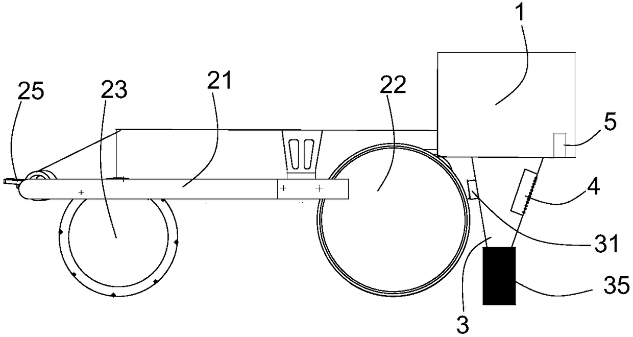
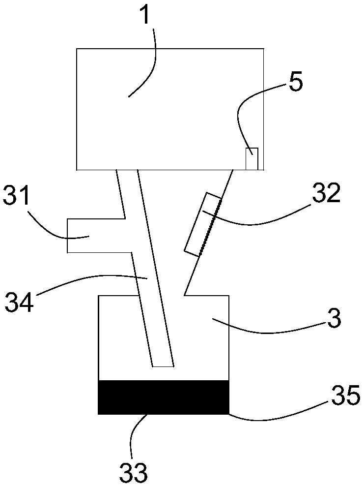
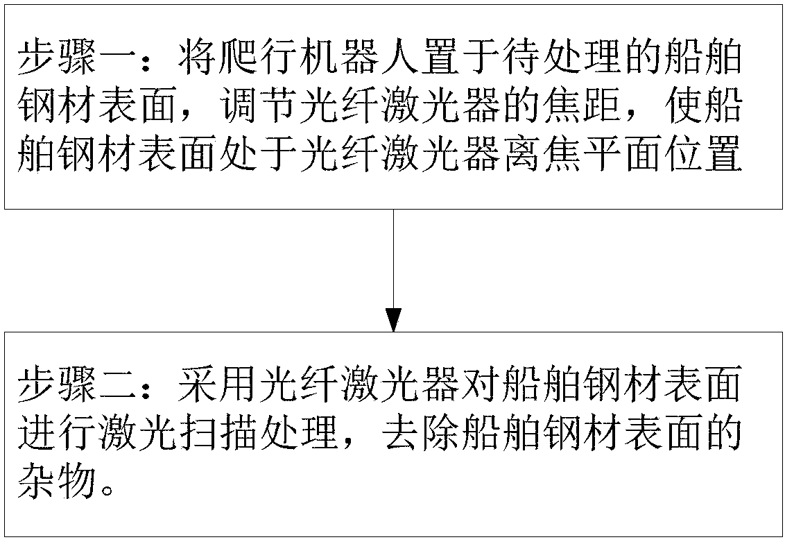

Image

  • Crawling robot and marine steel surface pretreatment process
  • Crawling robot and marine steel surface pretreatment process
  • Crawling robot and marine steel surface pretreatment process

Examples


Embodiment 1

[0041] The pretreatment process of the steel surface of the ship in this embodiment adopts the crawling robot described in the first aspect of the present invention.

[0042] In this embodiment, the wavelength of the fiber laser 1 is 1064nm, the crawling robot is placed on the surface of the ship steel that needs to be cleaned, and the focal length of the fiber laser 1 is adjusted so that the surface of the ship steel that needs to be cleaned is placed at the laser out-of-focus plane position. Impurities on the surface of ship steel are oxide scales, old coatings, oil stains, welding slag, dust and other sundries retained by the steel products; The distribution is relatively uniform, and when processing the surface of ship steel, if the laser energy is too concentrated, it is easy to damage the surface of the substrate, and a new oxide layer will be generated, and the surface roughness will be very low.

[0043] The cleaning process is as follows: simply clean the surface of t...

Embodiment 2

[0046] A pretreatment process for the surface of ship steel in this embodiment uses the crawling robot described in the first aspect of the present invention.

[0047] In this embodiment, the wavelength of the fiber laser 1 is 1064nm, the crawling robot is placed on the surface of the ship steel that needs to be cleaned, and the focal length of the fiber laser 1 is adjusted so that the surface of the ship steel that needs to be cleaned is placed at the laser out-of-focus plane position. Impurities on the surface of ship steel are oxide scales, old coatings, oil stains, welding slag, dust and other sundries left by the steel from the factory; the position of the laser from the focal plane is negative 10mm from the focal plane, which is located below the focal plane, so that the laser spot power density The distribution is relatively uniform, and when processing the surface of ship steel, if the laser energy is too concentrated, it is easy to damage the surface of the substrate, ...


PUM


Abstract

The invention provides a crawling robot and a marine steel surface pretreatment process. Fiber lasers are mounted on a vehicle body; the vehicle body is driven to move; laser cleaning is performed during moving; this mode is simple and efficient. The vehicle body has magnetic drive wheels so that the vehicle may travel in tight contact with the surface of a hull. The lasers mounted on the vehiclebody are kept evenly spaced from the surface of the hull. Fiber laser beams are used to perform laser scanning on the focal plane so that power density distribution is relatively uniform, and sundriesare cleaned without damaging steel base material. Compared with traditional grinding methods, the process employing noncontact processing has the advantages that laser processing causes no direct impact to marine steel so that no mechanical deformation occurs, laser processing precision is high so that the influence of human factors upon processing quality can be relieved, the processing efficiency is high, the quality is table and reliable, and the appearance is attractive.

Description

technical field [0001] The invention relates to the technical field of laser processing, in particular to a crawling robot and a pretreatment process for the surface of ship steel. Background technique [0002] Ships sailing on the ocean have always been in strong corrosive media, and their corrosion problems are very prominent, and the economic losses caused by this are quite serious. For ship steel structures, painting protective coatings and making full and effective use of marine shop primers are still one of the main means of corrosion protection today. [0003] When the steel leaves the factory, its surface is completely covered with a layer of hard oxide skin. The surface looks very hard, but in fact there are many gaps and mesh gaps, which cannot prevent the intrusion of water vapor and oxygen. After a long time, the gaps will start to corrode and spread to the surroundings, causing the scale to fall off. Therefore, the metal surface must be coated with a protective...

Claims


Application Information

Patent Timeline
Patent Type & Authority Applications(China)
IPC IPC(8): B62D57/024B63B59/10B08B7/00
CPCB08B7/0042B62D57/024B63B59/10
Inventor 郝磊金翔汪军熊凯凃宣梦张骆汪于涛
Owner WUHAN JINDUN LASER TECH CO LTD
Learn More