A kind of optical fiber fp air pressure sensor with optical vernier effect and preparation method thereof

A technology of air pressure sensor and vernier effect, which is applied to fluid pressure measurement, instruments, and measurement of fluid pressure using optical methods. It can solve the problems of expensive femtosecond lasers, expensive equipment and instruments, and low air pressure sensitivity, and achieve great freedom. Effects of spectral range, simple preparation method, and large measurement range

Active Publication Date: 2020-05-29
NANJING UNIV OF POSTS & TELECOMM
View PDF7 Cites 2 Cited by
  • Summary
  • Abstract
  • Description
  • Claims
  • Application Information

AI Technical Summary

Problems solved by technology

However, the thickness of the thin film coating needs to be precisely controlled, and the thin film deposition layer usually has a columnar crystal structure, which is not resistant to bending, and this technology is time-consuming, and the cost of equipment and instruments is also very expensive
Femtosecond laser micromachining technology can drill holes in the cladding of the quartz capillary, so that the punched air holes are connected to the central air hole to form an FP cavity, and directly punch holes in the core of the single-mode fiber, and then connect with another single-mode fiber. Optical fiber fusion splicing forms a bubble through the arc discharge of the fusion splicer, thereby producing an FP cavity. The preparation process of this method is simple and easy, but the parameters for the femtosecond laser drilling need to be accurately set, and the femtosecond laser is expensive, and the air pressure sensitivity Not high, the maximum sensitivity of the above scheme can only reach 3.592nm / MPa

Method used


Image

  • A kind of optical fiber fp air pressure sensor with optical vernier effect and preparation method thereof
  • A kind of optical fiber fp air pressure sensor with optical vernier effect and preparation method thereof
  • A kind of optical fiber fp air pressure sensor with optical vernier effect and preparation method thereof

Examples


Embodiment Construction

[0033] Below in conjunction with accompanying drawing, the present invention is described in further detail:

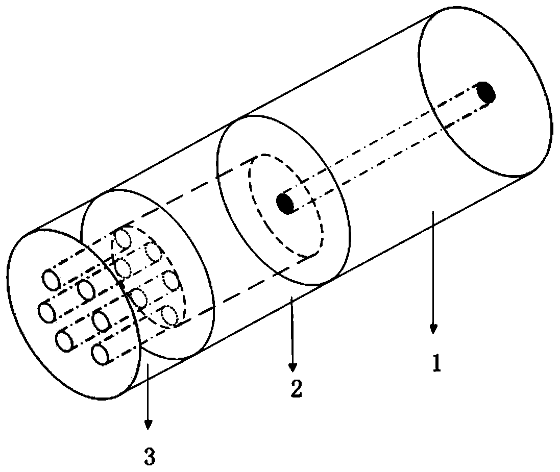
[0034] figure 1 It is a structural schematic diagram of an embodiment of the optical fiber FP air pressure sensor with optical vernier effect of the present invention. This embodiment includes a single-mode optical fiber 1 , a quartz capillary 2 , and a photonic crystal optical fiber 3 . The quartz capillary 2, the photonic crystal fiber 3 and the single-mode fiber 1 have the same outer diameter of 125 microns, and the inner diameter of the quartz capillary 2 is 40 microns. The cladding of photonic crystal fiber 3 is composed of six air holes arranged in a triangle, the diameter of the air hole is 3.4 microns, and the core is formed by missing one air hole, and the diameter of the core is 10 microns.

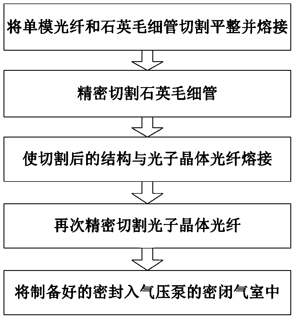
[0035] figure 2 It is a flowchart of an embodiment of the preparation method of the optical fiber FP air pressure sensor with optical vernier effect of the present ...


PUM

PropertyMeasurementUnit
lengthaaaaaaaaaa
lengthaaaaaaaaaa
Sensitivityaaaaaaaaaa

Abstract

The invention discloses an optical fiber FP air pressure sensor with optical vernier effect and a preparation method thereof. The sensor comprises a single-mode optical fiber, a quartz capillary and a photonic crystal optical fiber. The two ends of the quartz capillary are respectively connected to the respective ends of the single-mode fiber and the photonic crystal fiber by fusion; the other end of the photonic crystal fiber is directly connected to the outside world, and its hole structure is convenient for the outside gas to enter the fiber optic FP sensor. In the cavity, the quartz capillary and the photonic crystal fiber form two Fabry-Perot resonant cavities with vernier effect. A commercial optical fiber fusion splicer is used for preparation, the discharge time and intensity of the electrodes are well controlled to cascade the two types of optical fibers and the optical fiber is cut using a precision cutting device, and the length of the optical fiber is strictly controlled to produce a vernier effect. The optical fiber FP air pressure sensor of the invention has the advantages of small volume, simple preparation, strong adaptability, high sensitivity and wide application prospect.

Description

technical field [0001] The invention belongs to the technical field of optical fiber sensing and communication, and in particular relates to an optical fiber FP air pressure sensor with optical cursor effect and a preparation method thereof. Background technique [0002] As a kind of pressure sensor, the air pressure sensor has a wide range of application values ​​in national defense, maritime affairs, aerospace and civil use, and even some smart phones are embedded with air pressure sensors. The fiber optic air pressure sensor based on the Fabry-Perot interferometer (FPI) has attracted the attention of the industry because of its unique advantages. As we all know, optical fiber FPI usually includes a Fabry-Perot cavity composed of an optical fiber end face and a diaphragm end face. When the Fabry-Perot cavity is affected by external air pressure, the cavity of the Fabry-Perot cavity will change. Through The air pressure measurement can be realized by detecting the change o...

Claims


Application Information

Patent Timeline
Patent Type & Authority Patents(China)
IPC IPC(8): G01L11/02
CPCG01L11/025
Inventor 孙兵韩智天张祖兴韦玮
Owner NANJING UNIV OF POSTS & TELECOMM
Why Eureka
Try Eureka